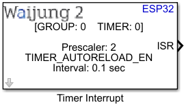
How this block appears in a Simulink model?
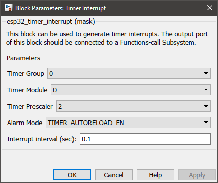
What can be configured?
Configuration Parameter |
Selectable Option/Value |
Description |
Timer group |
0--1 |
Select timer group |
Module |
0--1 |
Select timer module |
Timer pre-scaler |
2--4--8--16--32--64--128 |
How quickly the timer’s counter is “ticking”. This set the divider, that will be used as a divisor of the incoming 80 MHz APB_CLK clock. |
Alarm mode |
TIMER_AUTO_RELOAD_EN--TIMER_AUTO_RELOAD_DIS |
Enable or disable auto-reload of the alarm. |
Interrupt interval (sec) |
|
Select the interrupt interval in seconds |
INPUT/ OUTPUT Port
Port Name |
Date Type |
Description |
ISR |
Function-Call |
ISR port will output a logic ‘true’ signal that could activate a function-call subsystem in Simulink. |
When to use this block?
This block can be used to set up an Interrupt Service Routine (ISR) that could be triggered by a built-in timer module in the ESP32.
How does this block work?
The ESP32 chip contains two hardware timer groups. Each group has two general-purpose hardware timer(s). They are all 64-bit generic timers based on 16-bit pre-scalers and 64-bit up / down counters which are capable of being auto-reloaded. By default, the timer counter is set to 0 and is counted upwards. The alarm is also enabled by default while giving the user the ability to enable or disable auto-reload of the alarm.
Demo
Demo file : esp32_timer_interrupt_demo.slx
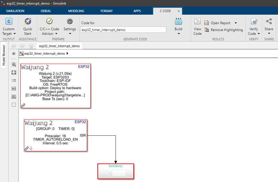
Description
This example shows how to use the Timer interrupt block. In this model an interrupt service routine (ISR) is called at a 0.5-second interval. Within the ISR, a GPIO pin is toggled to indicate the interrupt call.
Setup
An oscilloscope should be connected to the GPIO pin specified in the model (in the example GPIO Pin 2 is selected.)
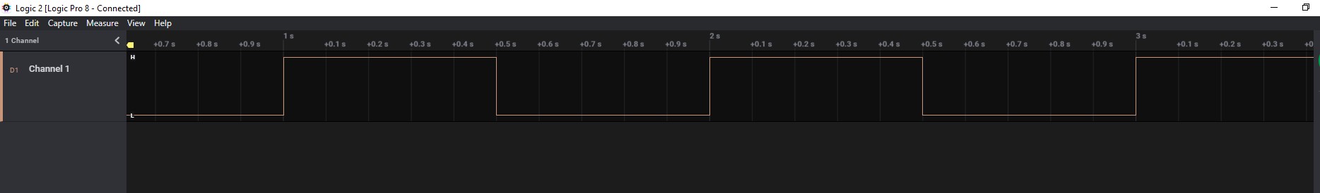
What should be happening?
After the model file is compiled and uploaded to the ESP32 board, the following output can be seen on the oscilloscope.