Design overview
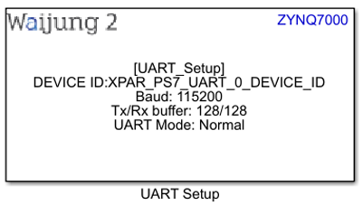
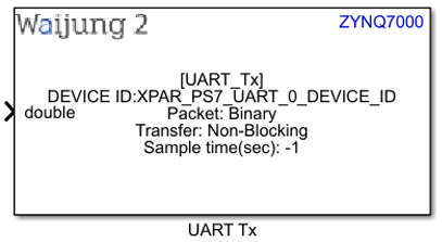
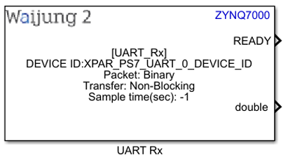
UART block appearance in a Simulink model,
UART Setup block
UART Tx block
UART Rx block
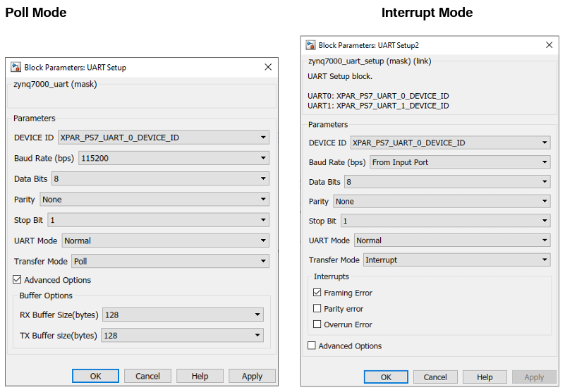
UART block mask overview,
UART Setup block
UART Tx block
UART Rx block
UART block input interfaces
UART Setup block
Name |
Type |
Range |
Description |
Baud rate(bps) |
uint32 |
min: 110, max: 6240000 |
This will appear if the Baud rate is selected as From Input Port. |
UART Tx block
Name |
Type |
Range |
Description |
||||||||
All data input ports |
|
Depends on the datatype of the Input port |
|
UART block output interfaces
UART Setup block
Name |
Type |
Range |
Description |
IRQ |
Function-call |
|
This will appear when the Interrupt mode is enabled. Multiple interrupts are represented with a single Function-call output port. To split it to separate ports, use Demux block in Simulink. |
UART Rx block
Name |
Type |
Range |
Description |
||||||||
READY |
uint8 |
0 - 1 |
This port is used to get the ready signal once the data received. |
||||||||
Len |
uint16 |
0 – 65535 (Depends on the receive data) |
This shows the length of the received data when the Packet mode is Read Line or Raw Buffer |
||||||||
All data output ports |
|
Depends on the datatype of the Input port |
This will appear if the Baud rate is selected as From Input Port. |
UART block behavior
UART block uses the Xilinx UARTPS Driver to perform the UART communication. Tx and Rx pins are configured using ether MIO or EMIO pins. This should be configured using Vivado Design Suite in the design stage. This block supports both Poll and Interrupt modes and in the interrupt mode the interrupt signal(s) will be transferred using Function-call output port. To change the baud rate of the UART module in the runtime using an input port, the UART Setup block should be placed in an Enabled subsystem. Once the subsystem is disabled and enabled the baud rate will be changed to the value which is specified in the input port. The UART module can be disabled (stop the communication) by disabling the Enabled subsystem of the relevant UART Setup block.
UART block configuration
UART Setup Block
Configuration Parameter |
Selectable Option/Value |
Default Value |
Description |
||||||||||||
DEVICE ID |
|
Depends on the Hardware design. If both UART modules are enabled, by default XPAR_PS7_UART_0_DEVICE_ID is selected |
Depending on the peripheral availability in your hardware design created using the Vivado Design Suite, available device-ids will be shown. |
||||||||||||
Baud Rate(bps) |
|
115200 |
If From Input Port is selected, the baud rate can be configured using input port. |
||||||||||||
Data Bits |
|
8 |
|
||||||||||||
Parity |
|
None |
Parity bit selection |
||||||||||||
Stop Bit |
|
1 |
Stop bit selection |
||||||||||||
UART Mode |
|
Normal |
UART Mode selection |
||||||||||||
Transfer Mode |
|
Poll |
Select Poll or Interrupt mode |
||||||||||||
Framing Error |
|
On |
Enable/Disable Framing Error interrupt by Checking/Unchecking. This will appear when the Transfer mode is Interrupt. |
||||||||||||
Parity Error |
|
Off |
Enable/Disable Parity Error interrupt by Checking/Unchecking. This will appear when the Transfer mode is Interrupt. |
||||||||||||
Overrun Error |
|
Off |
Enable/Disable Overrun Error interrupt by Checking/Unchecking. This will appear when the Transfer mode is Interrupt. |
||||||||||||
Advanced Options |
|
Off |
To show/hide RX buffer size and TX buffer size |
||||||||||||
RX Buffer Size |
|
128 |
Buffer size for Receiving data |
||||||||||||
TX Buffer Size |
|
128 |
Buffer size for Transmitting data |
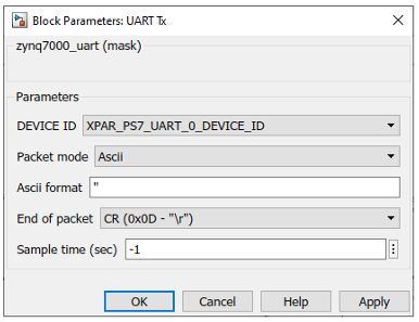
UART Tx block
Configuration Parameter |
Selectable Option/Value |
Default Value |
Description |
||||
DEVICE ID |
|
Depends on the Hardware design. If both UART modules are enabled, by default XPAR_PS7_UART_0_DEVICE_ID is selected |
Depending on the peripheral availability in your hardware design created using the Vivado Design Suite, available device-ids will be shown. |
||||
Packet Mode |
|
Binary |
Binary: This mode transmits the binary packet. Ascii: This block will generate a ascii buffer packet using sprintf, input data to port is parameter to sprintf corresponding to format specifier. Raw Buffer: Send the raw data from a single input port |
||||
Ascii format |
|
‘’ |
Scanf format specifier, start with %. Below is supported by block. %u, %i, %o, %x: input will be type of uint32 %d : input will be type of int32 %e, %g, %f : input will be type of single %c: input will be type of uint8. This will appear when the Packet mode is Ascii. |
||||
End of packet |
|
CR |
Terminator in ascii mode is used for detect the end of packet. This will appear when the Packet mode is Ascii |
||||
Binary header |
|
'7E 7E' |
Specify the Header pattern of packet to receive. Binary header can be neglected by adding ‘’ to the edit box. This will appear when the Packet mode is Binary |
||||
Binary terminator |
|
'03 03' |
Specify the terminator pattern of packet to receive. Binary terminator can be neglected by adding ‘’ to the edit box. This will appear when the Packet mode is Binary |
||||
Number of data port, type DOUBLE |
|
1 |
Number of data type uint8 in packet. This will appear when the Packet mode is Binary |
||||
Number of data port, type SINGLE |
|
0 |
Number of data type single in packet. This will appear when the Packet mode is Binary |
||||
Number of data port, type INT8 |
|
0 |
Number of data type int8 in packet. This will appear when the Packet mode is Binary |
||||
Number of data port, type UINT8 |
|
0 |
Number of data type uint8 in packet. This will appear when the Packet mode is Binary |
||||
Number of data port, type INT16 |
|
0 |
Number of data type int16 in packet. This will appear when the Packet mode is Binary |
||||
Number of data port, type UINT16 |
|
0 |
Number of data type uint16 in packet. This will appear when the Packet mode is Binary |
||||
Number of data port, type INT32 |
|
0 |
Number of data type int32 in packet. This will appear when the Packet mode is Binary |
||||
Number of data port, type UINT32 |
|
0 |
Number of data type uint32 in packet. This will appear when the Packet mode is Binary |
||||
Sample time |
|
-1 |
Set the sample time |
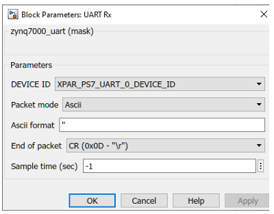
UART Rx block
Configuration Parameter |
Selectable Option/Value |
Default Value |
Description |
||||
DEVICE ID |
|
Depends on the Hardware design. If both UART modules are enabled, by default XPAR_PS7_UART_0_DEVICE_ID is selected |
Depending on the peripheral availability in your hardware design created using the Vivado Design Suite, available device-ids will be shown. |
||||
Packet Mode |
|
Binary |
Binary : This packet mode will accept the packets that contain binary data, by specifying the Header, Data format and Terminator of a packet to receive. The block will not accept the packet which contains invalid Header or Terminator. Ascii : This packet mode will accept the packets that contain ascii data (string), by specifying the sscanf format. The block will create the output port corresponding to the sscanf % format. Read Line: This mode can be used to receive the data with specified terminator and it read the data until the terminator and outputs Raw Buffer: This packet mode is used for receiving the raw string data and output using single port directly without processing the packet. |
||||
Ascii format |
|
|
Scanf format specifier, start with %. Below is supported by block. %u, %i, %o, %x: output will be type of uint32 %d : output will be type of int32 %e, %g, %f : output will be type of single %c: output will be type of uint8. This will appear when the Packet mode is Ascii. |
||||
End of packet |
|
CR |
Terminator in ascii mode is used for detect the end of packet. This will appear when the Packet mode is Ascii and Read Line |
||||
Binary header |
|
'7E 7E' |
Specify the Header pattern of packet to receive. Binary header can be neglected by adding ‘’ to the edit box. This will appear when the Packet mode is Binary |
||||
Binary terminator |
|
'03 03' |
Specify the terminator pattern of packet to receive. Binary terminator can be neglected by adding ‘’ to the edit box. This will appear when the Packet mode is Binary |
||||
Number of data port, type DOUBLE |
|
1 |
Number of data type uint8 in packet. This will appear when the Packet mode is Binary |
||||
Number of data port, type SINGLE |
|
0 |
Number of data type single in packet. This will appear when the Packet mode is Binary |
||||
Number of data port, type INT8 |
|
0 |
Number of data type int8 in packet. This will appear when the Packet mode is Binary |
||||
Number of data port, type UINT8 |
|
0 |
Number of data type uint8 in packet. This will appear when the Packet mode is Binary |
||||
Number of data port, type INT16 |
|
0 |
Number of data type int16 in packet. This will appear when the Packet mode is Binary |
||||
Number of data port, type UINT16 |
|
0 |
Number of data type uint16 in packet. This will appear when the Packet mode is Binary |
||||
Number of data port, type INT32 |
|
0 |
Number of data type int32 in packet. This will appear when the Packet mode is Binary |
||||
Number of data port, type UINT32 |
|
0 |
Number of data type uint32 in packet. This will appear when the Packet mode is Binary |
||||
Sample time |
|
-1 |
Set the sample time |
Typical application
Several demo files are provided at:
[<waijung2 installation directory>\waijung2\targets\zynq7000\demo\uart_demo]
To load the model file run the following commands in the Matlab Command Window:
•Demo 1: waijung2.openDemoInCurrentFolder('zynq7000', 'uart_demo1')
•Demo 2: waijung2.openDemoInCurrentFolder('zynq7000', 'uart_demo2')
•Demo 3: waijung2.openDemoInCurrentFolder('zynq7000', 'uart_demo3')