Design overview
TCP
TCP receive mode,
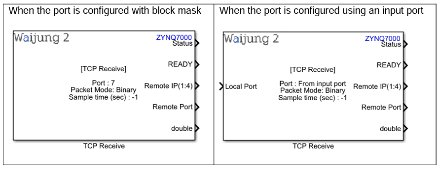
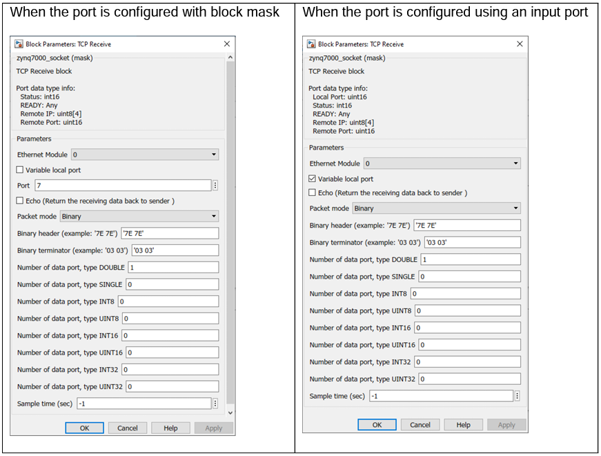
Block mask overview,
TCP send mode,
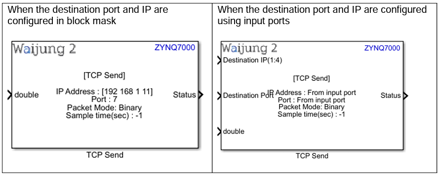
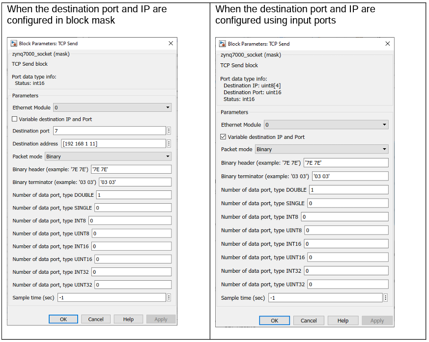
Block mask overview,
UDP
UDP receive mode,
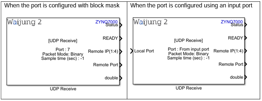
Block mask overview,

UDP send mode,
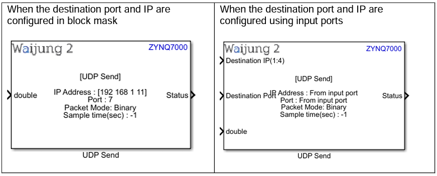
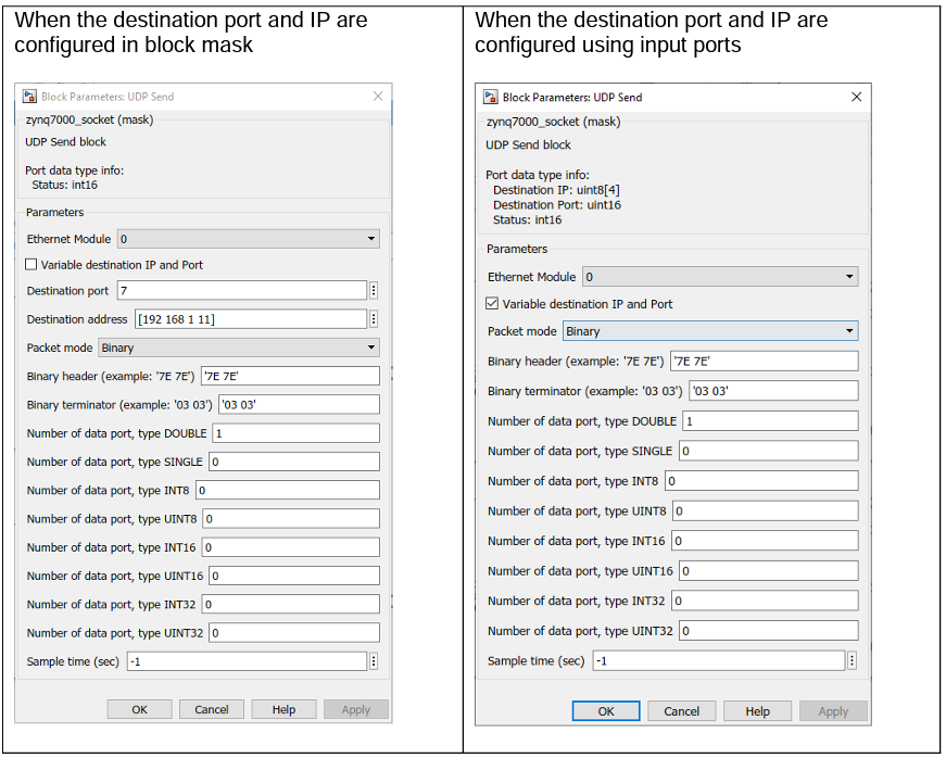
Block mask overview,
TCP UDP block input interfaces
TCP Receive
Name |
Type |
Range |
Description |
Local Port |
uint16 |
0 - 65535 |
Configure the local Port number using input port |
TCP Send
Name |
Type |
Range |
Description |
||||||||
Destination Port |
uint16 |
0 - 65535 |
Configure the destination Port number using input port |
||||||||
Destination IP |
uint8 array (size of 4) |
0 – 255 |
Configure the destination IP address using input port |
||||||||
All data input ports |
|
Depends on the data type of the Input port |
|
UDP Receive
Name |
Type |
Range |
Description |
Local Port |
uint16 |
0 - 65535 |
Configure the local Port number using input port |
UDP Send
Name |
Type |
Range |
Description |
||||||||
Destination Port |
uint16 |
0 - 65535 |
Configure the destination Port number using input port |
||||||||
Destination IP |
uint8 array (size of 4) |
0 – 255 |
Configure the destination IP address using input port |
||||||||
All data input ports |
|
Depends on the data type of the Input port |
|
TCP UDP block output interfaces
TCP Receive
Name |
Type |
Range |
Description |
||||||||
Status |
int16 |
0 – (-16) |
0: No error, everything OK -1: Out of memory error -2: Buffer error -3: Timeout -4: Routing problem -5: Operation in progress -6: Illegal value -7: Operation would block -8: Address in use -9: Already connecting -10: Connection already established -11: Not connected -12: Low-level netif error -13: Connection aborted -14: Connection reset -15: Connection closed -16: Illegal argument |
||||||||
READY |
Any |
|
0: Not ready 1: Ready |
||||||||
Remote Port |
uint16 |
0 – 65535 |
Output the remote Port |
||||||||
Remote IP |
uint8 array (size of 4) |
0 – 255 |
Output the remote IP address |
||||||||
All data output ports |
|
Depends on the data type of the Output port |
|
TCP Send
Name |
Type |
Range |
Description |
Status |
int16 |
0 – (-16) |
0: No error, everything OK -1: Out of memory error -2: Buffer error -3: Timeout -4: Routing problem -5: Operation in progress -6: Illegal value -7: Operation would block -8: Address in use -9: Already connecting -10: Connection already established -11: Not connected -12: Low-level netif error -13: Connection aborted -14: Connection reset -15: Connection closed -16: Illegal argument |
UDP Receive
Name |
Type |
Range |
Description |
||||||||
Status |
int16 |
0 – (-16) |
0: No error, everything OK -1: Out of memory error -2: Buffer error -3: Timeout -4: Routing problem -5: Operation in progress -6: Illegal value -7: Operation would block -8: Address in use -9: Already connecting -10: Connection already established -11: Not connected -12: Low-level netif error -13: Connection aborted -14: Connection reset -15: Connection closed -16: Illegal argument |
||||||||
READY |
Any |
|
0: Not ready 1: Ready |
||||||||
Remote Port |
uint16 |
0 - 65535 |
Output the remote Port |
||||||||
Remote IP |
uint8 array (size of 4) |
0 – 255 |
Output the remote IP address |
||||||||
All data output ports |
|
Depends on the data type of the Output port |
|
UDP Send
Name |
Type |
Range |
Description |
Status |
int16 |
0 – (-16) |
0: No error, everything OK -1: Out of memory error -2: Buffer error -3: Timeout -4: Routing problem -5: Operation in progress -6: Illegal value -7: Operation would block -8: Address in use -9: Already connecting -10: Connection already established -11: Not connected -12: Low-level netif error -13: Connection aborted -14: Connection reset -15: Connection closed -16: Illegal argument |
TCP UDP block behavior
TCP UDP block uses the Lwip211 library to perform the TCP or UDP communication. TCP UDP Receive block represents lwip server with RAW API if it is Bareboard, otherwise it is Socket API. TCP UDP Send block represents lwip client with RAW API if it is Bareboard, otherwise it is Socket API. The Ethernet block is required to initialize the Ethernet module prior to using TCP UDP block. Ethernet pins are configured using ether MIO or EMIO pins. This should be configured using Vivado Design Suite in the hardware reference design stage.
In receive mode, the server will initialize with the given port (Local port) and keeps listening to that port throughout the application even though a client is connected or not. In the send mode when the zynq7000 acts as a client, it will connect to the given destination port and the IP address when the client is initializing. Client prefers persistent connection and if the external server is disconnected from the client, it will reinitialize the client in the next execution cycle with given destination IP address and the port.
TCP UDP block configuration
TCP Receive
Configuration Parameter |
Selectable Option/Value |
Default Value |
Description |
||||
Ethernet module |
|
Depends on the Hardware reference design. If both Ethernet modules are enabled, by default 0 is selected. |
Depending on the peripheral availability in your hardware design created using the Vivado Design Suite, available Ethernet module will be shown. |
||||
Variable local port |
|
Off |
Configure the Port number using an input port if this parameter is enabled. |
||||
Port |
|
7 |
This parameter is used to configure the Port number through the block mask. This will only appear when the Variable local port is disabled. |
||||
Echo |
|
Off |
Echo mode is used to return the receiving data back to the sender for debugging purposes. |
||||
Packet Mode |
|
Binary |
Binary : This packet mode will accept the packets that contain binary data, by specifying the Header, Data format and Terminator of a packet to receive. The block will not accept the packet which contains invalid Header or Terminator. Ascii : This packet mode will accept the packets that contain ascii data (string), by specifying the sscanf format. The block will create the output port corresponding to the sscanf % format. Read Line: This mode can be used to receive the data with specified terminator and it read the data until the terminator and outputs Raw Buffer: This packet mode is used for receiving the raw string data and output using single port directly without processing the packet. |
||||
Ascii format |
|
|
Scanf format specifier, start with %. Below is supported by block. %u, %i, %o, %x: output will be type of uint32 %d : output will be type of int32 %e, %g, %f : output will be type of single %c: output will be type of uint8 or character. This will appear when the Packet mode is set to Ascii. |
||||
End of packet |
|
CR |
Terminator in ascii mode is used for detect the end of packet. This will appear when the Packet mode is Ascii and Read Line |
||||
Binary header |
|
'7E 7E' |
Specify the Header pattern of packet to receive. Binary header can be neglected by adding ‘’ to the edit box. This will appear when the Packet mode is Binary |
||||
Binary terminator |
|
'03 03' |
Specify the terminator pattern of packet to receive. Binary terminator can be neglected by adding ‘’ to the edit box. This will appear when the Packet mode is Binary |
||||
Number of data port, type DOUBLE |
|
1 |
Number of data type uint8 in packet. This will appear when the Packet mode is Binary |
||||
Number of data port, type SINGLE |
|
0 |
Number of data type single in packet. This will appear when the Packet mode is Binary |
||||
Number of data port, type INT8 |
|
0 |
Number of data type int8 in packet. This will appear when the Packet mode is Binary |
||||
Number of data port, type UINT8 |
|
0 |
Number of data type uint8 in packet. This will appear when the Packet mode is Binary |
||||
Number of data port, type INT16 |
|
0 |
Number of data type int16 in packet. This will appear when the Packet mode is Binary |
||||
Number of data port, type UINT16 |
|
0 |
Number of data type uint16 in packet. This will appear when the Packet mode is Binary |
||||
Number of data port, type INT32 |
|
0 |
Number of data type int32 in packet. This will appear when the Packet mode is Binary |
||||
Number of data port, type UINT32 |
|
0 |
Number of data type uint32 in packet. This will appear when the Packet mode is Binary |
||||
Data size |
|
10 |
This will appear when the packet mode is set to Real Line or Raw Buffer or Ascii. This is used to set the output buffer size for received data. |
||||
Sample time |
|
-1 |
Set the sample time |
TCP Send
Configuration Parameter |
Selectable Option/Value |
Default Value |
Description |
||||
Ethernet module |
|
Depends on the Hardware design. If both Ethernet modules are enabled, by default 0 is selected. |
Depending on the peripheral availability in your hardware design created using the Vivado Design Suite, available Ethernet module will be shown. |
||||
Variable destination IP and Port |
|
Off |
Configure the IP and Port number of the destination device using input ports if this parameter is enabled. |
||||
Destination port |
|
7 |
This parameter is used to configure the Port number of the destination through the block mask. This will appear when the Variable destination IP and Port is disabled. |
||||
Destination IP |
|
[192 168 1 11] |
This parameter is used to configure the IP address of the destination through the block mask. This will appear when the Variable destination IP and Port is disabled. This should be defined as a vector with size of 4. |
||||
Packet Mode |
|
Binary |
Binary: This packet mode will accept the packets that contain binary data, by specifying the Header, Data format and Terminator of a packet to send. Ascii: This packet mode will accept the packets that contain ascii data (string), by specifying the sscanf format. The block will create the input ports corresponding to the sscanf % format. Raw Buffer: This packet mode is used for sending the raw data and input using single port directly without processing the packet. |
||||
Ascii format |
|
|
Scanf format specifier, start with %. Below is supported by block. %u, %i, %o, %x: input will be type of uint32 %d: input will be type of int32 %e, %g, %f: input will be type of single %c: input will be type of uint8 or character. This will appear when the Packet mode is set to Ascii. |
||||
End of packet |
|
CR |
Terminator in ascii mode is used for set the end of packet. This will appear when the Packet mode is Ascii and Read Line |
||||
Binary header |
|
'7E 7E' |
Specify the Header pattern of packet to send. Binary header can be neglected by adding ‘’ to the edit box. This will appear when the Packet mode is Binary |
||||
Binary terminator |
|
'03 03' |
Specify the terminator pattern of packet to send. Binary terminator can be neglected by adding ‘’ to the edit box. This will appear when the Packet mode is Binary |
||||
Number of data port, type DOUBLE |
|
1 |
Number of data type uint8 in packet. This will appear when the Packet mode is Binary |
||||
Number of data port, type SINGLE |
|
0 |
Number of data type single in packet. This will appear when the Packet mode is Binary |
||||
Number of data port, type INT8 |
|
0 |
Number of data type int8 in packet. This will appear when the Packet mode is Binary |
||||
Number of data port, type UINT8 |
|
0 |
Number of data type uint8 in packet. This will appear when the Packet mode is Binary |
||||
Number of data port, type INT16 |
|
0 |
Number of data type int16 in packet. This will appear when the Packet mode is Binary |
||||
Number of data port, type UINT16 |
|
0 |
Number of data type uint16 in packet. This will appear when the Packet mode is Binary |
||||
Number of data port, type INT32 |
|
0 |
Number of data type int32 in packet. This will appear when the Packet mode is Binary |
||||
Number of data port, type UINT32 |
|
0 |
Number of data type uint32 in packet. This will appear when the Packet mode is Binary |
||||
Data size |
|
10 |
This will appear when the packet mode is set to Raw Buffer or Ascii. This is used to set the input buffer size for send data. |
||||
Sample time |
|
-1 |
Set the sample time |
UDP Receive
Configuration Parameter |
Selectable Option/Value |
Default Value |
Description |
||||
Ethernet module |
|
Depends on the Hardware design. If both Ethernet modules are enabled, by default 0 is selected. |
Depending on the peripheral availability in your hardware design created using the Vivado Design Suite, available Ethernet module will be shown. |
||||
Variable local port |
|
Off |
Configure the Port number using an input port if this parameter is enabled. |
||||
Port |
|
7 |
This parameter is used to configure the Port number through the block mask. This will appear when the Variable local port is disabled. |
||||
Echo |
|
Off |
Echo mode is used to return the receiving data back to the sender for debugging purposes. |
||||
Packet Mode |
|
Binary |
Binary : This packet mode will accept the packets that contain binary data, by specifying the Header, Data format and Terminator of a packet to receive. The block will not accept the packet which contains invalid Header or Terminator. Ascii : This packet mode will accept the packets that contain ascii data (string), by specifying the sscanf format. The block will create the output port corresponding to the sscanf % format. Read Line: This mode can be used to receive the data with specified terminator and it read the data until the terminator and outputs Raw Buffer: This packet mode is used for receiving the raw string data and output using single port directly without processing the packet. |
||||
Ascii format |
|
|
Scanf format specifier, start with %. Below is supported by block. %u, %i, %o, %x: output will be type of uint32 %d : output will be type of int32 %e, %g, %f : output will be type of single %c: output will be type of uint8 or character. This will appear when the Packet mode is set to Ascii. |
||||
End of packet |
|
CR |
Terminator in ascii mode is used for detect the end of packet. This will appear when the Packet mode is Ascii and Read Line |
||||
Binary header |
|
'7E 7E' |
Specify the Header pattern of packet to receive. Binary header can be neglected by adding ‘’ to the edit box. This will appear when the Packet mode is Binary |
||||
Binary terminator |
|
'03 03' |
Specify the terminator pattern of packet to receive. Binary terminator can be neglected by adding ‘’ to the edit box. This will appear when the Packet mode is Binary |
||||
Number of data port, type DOUBLE |
|
1 |
Number of data type uint8 in packet. This will appear when the Packet mode is Binary |
||||
Number of data port, type SINGLE |
|
0 |
Number of data type single in packet. This will appear when the Packet mode is Binary |
||||
Number of data port, type INT8 |
|
0 |
Number of data type int8 in packet. This will appear when the Packet mode is Binary |
||||
Number of data port, type UINT8 |
|
0 |
Number of data type uint8 in packet. This will appear when the Packet mode is Binary |
||||
Number of data port, type INT16 |
|
0 |
Number of data type int16 in packet. This will appear when the Packet mode is Binary |
||||
Number of data port, type UINT16 |
|
0 |
Number of data type uint16 in packet. This will appear when the Packet mode is Binary |
||||
Number of data port, type INT32 |
|
0 |
Number of data type int32 in packet. This will appear when the Packet mode is Binary |
||||
Number of data port, type UINT32 |
|
0 |
Number of data type uint32 in packet. This will appear when the Packet mode is Binary |
||||
Data size |
|
10 |
This will appear when the packet mode is set to Real Line or Raw Buffer or Ascii. This is used to set the output buffer size for received data. |
||||
Sample time |
|
-1 |
Set the sample time |
UDP Send
Configuration Parameter |
Selectable Option/Value |
Default Value |
Description |
||||
Ethernet module |
|
Depends on the Hardware design. If both Ethernet modules are enabled, by default 0 is selected. |
Depending on the peripheral availability in your hardware design created using the Vivado Design Suite, available Ethernet module will be shown. |
||||
Variable destination IP and Port |
|
Off |
Configure the IP and Port number of the destination device using input ports if this parameter is enabled. |
||||
Destination port |
|
7 |
This parameter is used to configure the Port number of the destination through the block mask. This will appear when the Variable destination IP and Port is disabled. |
||||
Destination IP |
|
[192 168 1 11] |
This parameter is used to configure the IP address of the destination through the block mask. This will appear when the Variable destination IP and Port is disabled. This should be defined as a vector with size of 4. |
||||
Packet Mode |
|
Binary |
Binary: This packet mode will accept the packets that contain binary data, by specifying the Header, Data format and Terminator of a packet to send. Ascii: This packet mode will accept the packets that contain ascii data (string), by specifying the sscanf format. The block will create the input ports corresponding to the sscanf % format. Raw Buffer: This packet mode is used for sending the raw data and input using single port directly without processing the packet. |
||||
Ascii format |
|
|
Scanf format specifier, start with %. Below is supported by block. %u, %i, %o, %x: input will be type of uint32 %d: input will be type of int32 %e, %g, %f: input will be type of single %c: input will be type of uint8 or character. This will appear when the Packet mode is set to Ascii. |
||||
End of packet |
|
CR |
Terminator in ascii mode is used for set the end of packet. This will appear when the Packet mode is Ascii and Read Line |
||||
Binary header |
|
'7E 7E' |
Specify the Header pattern of packet to send. Binary header can be neglected by adding ‘’ to the edit box. This will appear when the Packet mode is Binary |
||||
Binary terminator |
|
'03 03' |
Specify the terminator pattern of packet to send. Binary terminator can be neglected by adding ‘’ to the edit box. This will appear when the Packet mode is Binary |
||||
Number of data port, type DOUBLE |
|
1 |
Number of data type uint8 in packet. This will appear when the Packet mode is Binary |
||||
Number of data port, type SINGLE |
|
0 |
Number of data type single in packet. This will appear when the Packet mode is Binary |
||||
Number of data port, type INT8 |
|
0 |
Number of data type int8 in packet. This will appear when the Packet mode is Binary |
||||
Number of data port, type UINT8 |
|
0 |
Number of data type uint8 in packet. This will appear when the Packet mode is Binary |
||||
Number of data port, type INT16 |
|
0 |
Number of data type int16 in packet. This will appear when the Packet mode is Binary |
||||
Number of data port, type UINT16 |
|
0 |
Number of data type uint16 in packet. This will appear when the Packet mode is Binary |
||||
Number of data port, type INT32 |
|
0 |
Number of data type int32 in packet. This will appear when the Packet mode is Binary |
||||
Number of data port, type UINT32 |
|
0 |
Number of data type uint32 in packet. This will appear when the Packet mode is Binary |
||||
Data size |
|
10 |
This will appear when the packet mode is set to Raw Buffer or Ascii. This is used to set the input buffer size for send data. |
||||
Sample time |
|
-1 |
Set the sample time |
TCP UDP block limitation
Each TCP UDP Receive block represents a server with given port and each TCP UDP Send block represents a client.
Typical application
[<waijung2 installation directory>\waijung2\targets\zynq7000\demo\socket_demo]
To load the model file run the following commands in the Matlab Command Window:
• Demo: waijung2.openDemoInCurrentFolder('zynq7000', 'socket_demo')