Design overview
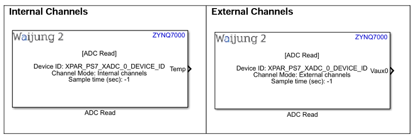
ADC block appearance in a Simulink model,
ADC Setup block
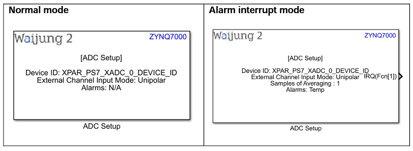
ADC Read block
ADC block mask overview,
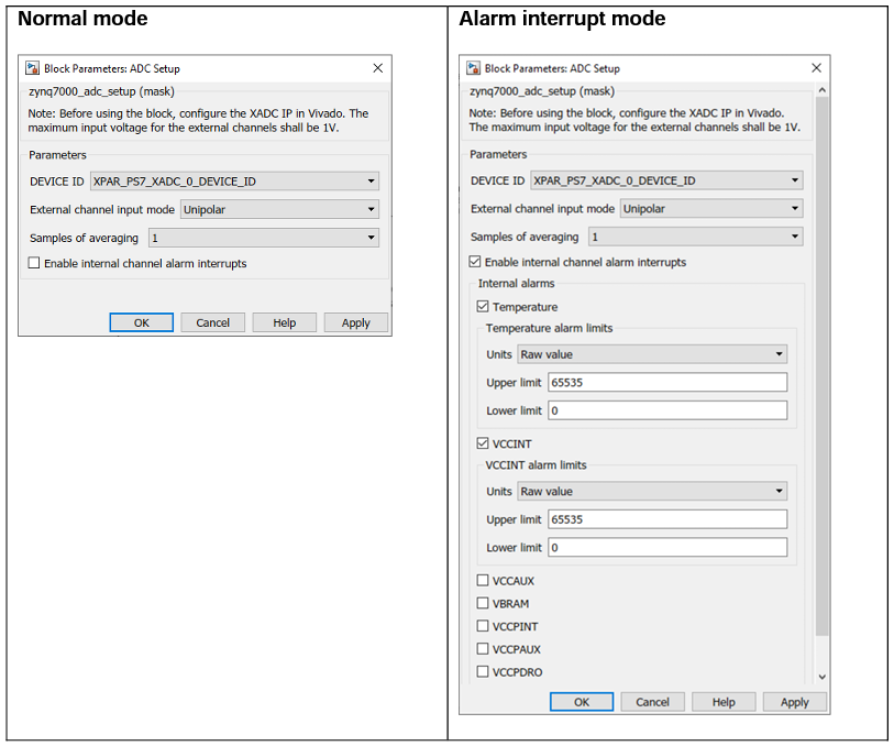
ADC Setup block
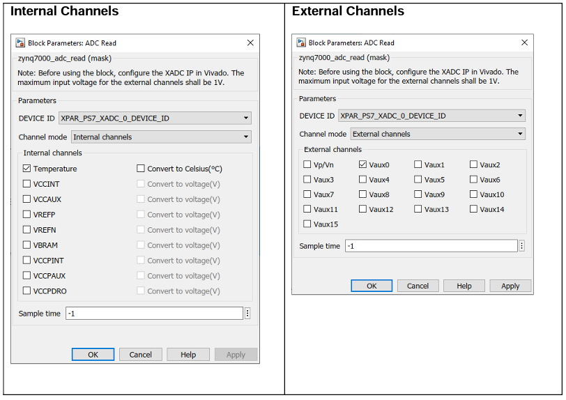
ADC Read block
ADC block output interfaces
ADC Setup block
Name |
Type |
Range |
Description |
IRQ |
Function-call |
|
This will appear when the Alarm interrupt mode is enabled. Multiple interrupts are represented with a single Function-call output port. To split it to separate ports, use Demux block in Simulink. |
ADC Read block
Name |
Type |
Range |
Description |
||
All data output ports |
|
Depends on the measurement. Refer the following table for the data range
|
By default, output data will be uint16 value which gives the Raw value. If the measurement needs to be converted to a physical measurement (voltage or temperature), the data type will be single. The measurement conversion is only supported for internal channels. |
Data range
Channel mode |
Input mode |
Units |
Range |
Internal |
Unipolar |
Raw value |
0 to 65536 |
Physical value |
For temperature, -273.15 to 230.82 °C For voltage, 0 to 3V |
||
External |
Unipolar |
Raw value |
0 to 65536 |
Bipolar |
ADC block behavior
ADC block consists with two modes; Setup and read. It uses the Xilinx XADCPS Driver to setup and to get the ADC readings of internal and external channels. ADC external auxiliary pins are configured using package pins. This should be configured using Vivado Design Suite in the design stage. This block supports internal channel alarm interrupt mode and in this mode the interrupt signal(s) will be directed through Function-call output port. If multiple interrupts are available, those signals should be separated using Demux Simulink block.
ADC block configuration
ADC Setup Block
Configuration Parameter |
Selectable Option/Value |
Default Value |
Description |
||||
DEVICE ID |
|
XPAR_PS7_XADC_0_DEVICE_ID |
There is only one ADC module available on Zynq-7000 |
||||
External channel input mode |
|
Unipolar |
|
||||
Samples of averaging |
|
1 |
Number of samples which need to be averaged. |
||||
Enable internal channel alarm interrupts |
|
off |
Enable alarm interrupt mode for internal ADC channels. |
||||
Temperature |
|
off |
Enable the alarm for temperature. This will show once Enable internal channel alarm interrupts is enabled. Temperature alarm interrupt signal will be active if the measurement is greater than the Upper limit. Alarm interrupt will be reset when the measurement is lower than Lower limit. |
||||
Units |
|
Raw value |
Input the alarm upper limit and lower limit in raw value or in Celsius. This will show once the Temperature alarm is enabled. The range for Upper limit or Lower limit will be 0 to 65536 if the units are Raw value. If it is in Celsius the range will be -273.15 to 230.82 |
||||
Upper limit |
|
65536 |
Input the upper limit of the Temperature alarm. This will show once the Temperature alarm is enabled. |
||||
Lower limit |
|
0 |
Input the lower limit of the Temperature alarm. This will show once the Temperature alarm is enabled. |
||||
VCCINT |
|
off |
Enable the alarm for VCCINT. This will show once Enable internal channel alarms is enabled. This alarm interrupt will be active if the reading is greater than Upper limit or lower than Lower limit. The alarm interrupt will be reset when the reading is in between Lower limit and the Upper limit. |
||||
Units |
|
Raw value |
Input the alarm upper limit and lower limit in bit value or in Volt. This will show once the VCCINT alarm is enabled. The range for Upper limit or Lower limit will be 0 to 65536 if the units are Raw value. If it is in Voltage the range will be 0 to 3.0. |
||||
Upper limit |
|
0 |
Input the upper limit of the VCCINT alarm. This will show once the VCCINT alarm is enabled. |
||||
Lower limit |
|
65536 |
Input the lower limit of the VCCINT alarm. This will show once the VCCINT alarm is enabled. |
||||
VCCAUX |
|
off |
Enable the alarm for VCCAUX. This will show once Enable internal channel alarms is enabled. This alarm interrupt will be active if the reading is greater than Upper limit or lower than Lower limit. The alarm interrupt will be reset when the reading is in between Lower limit and the Upper limit. |
||||
Units |
|
Raw value |
Input the alarm upper limit and lower limit in bit value or in Volt. This will show once the VCCAUX alarm is enabled. The range for Upper limit or Lower limit will be 0 to 65536 if the units are Raw value. If it is in Voltage the range will be 0 to 3.0. |
||||
Upper limit |
|
65536 |
Input the upper limit of the VCCAUX alarm. This will show once the VCCAUX alarm is enabled. |
||||
Lower limit |
|
0 |
Input the lower limit of the VCCAUX alarm. This will show once the VCCAUX alarm is enabled. |
||||
VBRAM |
|
off |
Enable the alarm for VBRAM. This will show once Enable internal channel alarms is enabled. This alarm interrupt will be active if the reading is greater than Upper limit or lower than Lower limit. The alarm interrupt will be reset when the reading is in between Lower limit and the Upper limit. |
||||
Units |
|
Raw value |
Input the alarm upper limit and lower limit in bit value or in Volt. This will show once the VBRAM alarm is enabled. The range for Upper limit or Lower limit will be 0 to 65536 if the units are Raw value. If it is in Voltage the range will be 0 to 3.0. |
||||
Upper limit |
|
65536 |
Input the upper limit of the VBRAM alarm. This will show once the VBRAM alarm is enabled. |
||||
Lower limit |
|
0 |
Input the lower limit of the VBRAM alarm. This will show once the VBRAM alarm is enabled. |
||||
VCCPINT |
|
off |
Enable the alarm for VCCPINT. This will show once Enable internal channel alarms is enabled. This alarm interrupt will be active if the reading is greater than Upper limit or lower than Lower limit. The alarm interrupt will be reset when the reading is in between Lower limit and the Upper limit.
|
||||
Units |
|
Raw value |
Input the alarm upper limit and lower limit in bit value or in Volt. This will show once the VCCPINT alarm is enabled. The range for Upper limit or Lower limit will be 0 to 65536 if the units are Raw value. If it is in Voltage the range will be 0 to 3.0. |
||||
Upper limit |
|
65536 |
Input the upper limit of the VCCPINT alarm. This will show once the VCCPINT alarm is enabled. |
||||
Lower limit |
|
0 |
Input the lower limit of the VCCPINT alarm. This will show once the VCCPINT alarm is enabled. |
||||
VCCPAUX |
|
off |
Enable the alarm for VCCPAUX. This will show once Enable internal channel alarms is enabled. This alarm interrupt will be active if the reading is greater than Upper limit or lower than Lower limit. The alarm interrupt will be reset when the reading is in between Lower limit and the Upper limit. |
||||
Units |
|
Raw value |
Input the alarm upper limit and lower limit in bit value or in Volt. This will show once the VCCPAUX alarm is enabled. The range for Upper limit or Lower limit will be 0 to 65536 if the units are Raw value. If it is in Voltage the range will be 0 to 3.0. |
||||
Upper limit |
|
65536 |
Input the upper limit of the VCCPAUX alarm. This will show once the VCCPAUX alarm is enabled. |
||||
Lower limit
|
|
0 |
Input the lower limit of the VCCPAUX alarm. This will show once the VCCPAUX alarm is enabled. |
||||
VCCPDRO |
|
off |
Enable the alarm for VCCPDRO. This will show once Enable internal channel alarms is enabled. This alarm interrupt will be active if the reading is greater than Upper limit or lower than Lower limit. The alarm interrupt will be reset when the reading is in between Lower limit and the Upper limit. |
||||
Units |
|
Raw value |
Input the alarm upper limit and lower limit in bit value or in Volt. This will show once the VCCPDRO alarm is enabled. The range for Upper limit or Lower limit will be 0 to 65536 if the units are Raw value. If it is in Voltage the range will be 0 to 3.0. |
||||
Upper limit |
|
65536 |
Input the upper limit of the VCCPDRO alarm. This will show once the VCCPDRO alarm is enabled. |
||||
Lower limit |
|
0 |
Input the lower limit of the VCCPDRO alarm. This will show once the VCCPDRO alarm is enabled. |
ADC Read block
Configuration Parameter |
Selectable Option/Value |
Default Value |
Description |
||
DEVICE ID |
|
XPAR_PS7_XADC_0_DEVICE_ID |
There is only one ADC module available on Zynq-7000 |
||
Channel mode |
|
Internal channels |
Select the channel mode as Internal or External to get ADC readings from internal channels or external channels
|
||
All internal and external channels |
|
off |
Select the required internal or external channel to measure. |
||
Convert to Celsius(°C) |
|
off |
Convert the internal ADC temperature readings to Celsius |
||
Convert to voltage(V) |
|
off |
Convert the internal ADC readings to Voltage. |
||
Sample time |
|
-1 |
Set the sample time |
ADC block limitation
All the analog input channels are differential and each channel has two inputs (VP and VN). All the internal input channels support Unipolar mode and the external channels support both Unipolar and Bipolar. The maximum conversion rate specified for the ADC is 1 MSPS or a conversion time of 1 µs. For external ADC channels, the nominal analog input range to the ADCs is 0V to 1V if it is in Unipolar mode. For the Bipolar mode, it is -0.5V to 0.5V.
Typical application
Several demo files are provided at:
[<waijung2 installation directory>\waijung2\targets\zynq7000\demo\adc_demo]
To load the model file run the following commands in the Matlab Command Window:
•Demo 1: waijung2.openDemoInCurrentFolder('zynq7000', 'adc_demo1')
•Demo 2: waijung2.openDemoInCurrentFolder('zynq7000', 'adc_demo2')