Introduction
The Waijung 2, ZYNQ7000 embedded target allows the user for Code Verification and Validation in ZYNQ7000 using Processor-In-the-Loop(PIL) Simulation. Using this simulation mode, you can test whether your model and generated code are numerically equivalent. Simulink PIL supports three different simulation modes. For more information go to Code Verification and Validation with PIL.
Features
The PIL implementation support the following features,
●PIL simulation supports code execution profiling
●Supported OS:
○Bareboard
○FreeRTOS
●Supported communication interfaces:
○Serial
○TCP/IP
Limitations
When the PIL communication interface is serial, specified UART driver module blocks cannot be used in the model for other tasks.
When the PIL communication interface is TCP/IP, Ethernet driver blocks cannot be used in the model for other tasks. Additionally, when using this communication interface in BareBoard OS, Timer Interrupt driver cannot be used as well.
These conditions are automatically checked during the build process and an error is thrown to stop the build process.
The minimum sample time that PIL can simulate depends on the
●OS
●The drivers that you are going to test
PIL simulation in Waijung 2 ZYNQ7000 target only supports Model block simulation mode.
Configuration Parameters
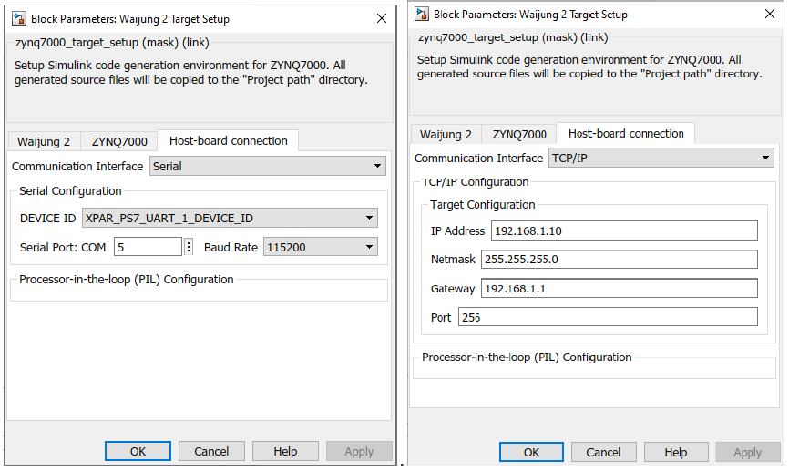
PIL host-target communication can be configured in the target setup block mask.
Configuration Parameter |
Selectable Option/Value |
Default Value |
Description |
||||
Communication Interface |
|
Serial |
Select the communication interface external mode uses to exchange data between the host and the target hardware. |
||||
DEVICE ID |
or
|
XPAR_PS7_UART_0_DEVICE_ID or XPAR_PS7_ETHERNET_0_DEVICE_ID |
Select the device ID of the driver module depends on the Communication interface as well as the Hardware reference design file (.xsa).
|
||||
Serial Port: COM |
|
20 |
Enter the ‘COM’ part to which the target is connected. |
||||
Baud Rate |
|
115200 |
Select the baud rate for serial communication. |
||||
IP Address |
|
192.168.1.10 |
Enter the IP address |
||||
Netmask |
|
255.255.255.0 |
Enter the netmask IP address |
||||
Gateway |
|
192.168.1.1 |
Enter the gateway IP address |
||||
Port |
|
256 |
Enter the network port |
||||
MAC address |
|
00-0a-35-00-01-02 |
Enter the MAC address |
Setting Up Simulink Model(s) for PIL Simulation
Two Simulink models are required for the PIL simulation using Model block Simulation mode; Reference model and Top model.
●Reference model
This model is used to contain all the blocks which are related to the task(algorithm) that should be run on the target. Add the required input and outputs using input ports and output ports
●Top model
Top model can be used to send the input signals to the reference model and monitor the output signals from the reference model. In addition to that, this model is used to simulate algorithms on the host and can be compared with the reference model outputs(Note: driver specific blocks cannot be simulated on the host).
Note: Model block is used on the top model to link the reference model with the top model.
The following steps are required to set up any simulink model for PIL simulation
In the Reference model,
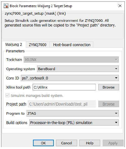
1.Add the Waijung2 Target Setup Block and browse the xsa file in the ZYNQ7000 tab.
2.Set the Build options to Processor-in-the-loop simulation in the Waijung2 tab and click Apply. Host-board connection tab would appear on the block mask.
3.From the Host-board connection tab, select the preferred communication interface i.e. serial, tcp/ip and fill in the necessary configurations for the selected interface.
4.Implement the algorithm for the target and add the required input and output ports and save the model
In the Top model,
1.Add the PIL Host Setup block
This block is only used to set required Model Configuration parameters in the Top model.
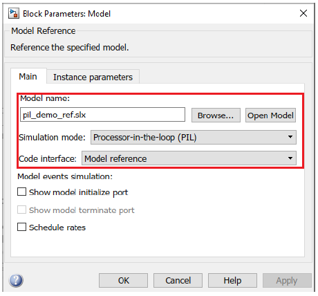
2.Add a Model block to link the Reference model. In the Model block mask,
a.Browse the reference model file
b.Change the Simulation mode to Processor-in-the-loop
c.Change the Code interface to Model reference
3.Connect the input and output port of the model block to required inputs(e.g: pulse generators, constant blocks,... ) and outputs(e.g: scope,....).
4.To enable the SIL/PIL toolstrip on Simulink go to Apps → SIL/PIL Manage
5.Then go to SIL/PIL tab
a.Change the Mode to Automated Verification
b.Change the System Under Test to Model blocks in SIL/PIL mode
c.Change the Top Model Mode to Normal
d.Set the Stop Time to finite value
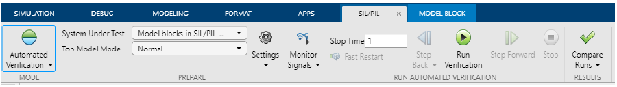
6.Save the model file and click on the Run Verification button on the SIL/PIL tab to build, compile and run the simulation.
7.Once the simulation is finished, open the scope or output source to see the simulation data.
8.If you need to see the code execution profiling report, in the Top model go to SIL/PIL tab → Compare Runs → Generate Report. It will generate a report about the execution profiling
Example
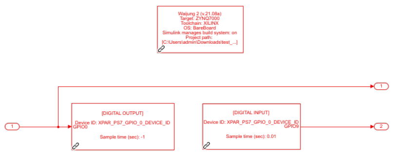
1.Reference model
Demo file location: [ waijung2 installation folder ]\targets\zynq7000\demo\pil_demo\pil_demo_ref.slx
2.Top model
Demo file location: [ waijung2 installation folder]\targets\zynq7000\demo\pil_demo\pil_demo_top.slx]
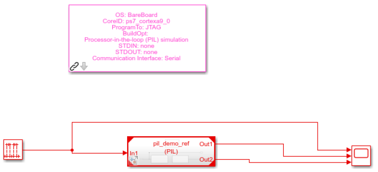
Description
This is a simple example to showcase the capabilities of using the PIL feature. In this model, GPIO Out block is used to generate the signal from MIO0 pin which is input from the Top model(pil_demo_top.slx) and the GPIO Input block is used to read the MIO9 and output that signal to the Top model. And in addition to that, the input signal is directly sent to the Top model.
The demo file is configured to use serial as the communication interface for PIL simulation.
Note: Before running the simulation, change the COM port from the Waijung2 Target Setup Block mask and short circuit the MIO0 and MIO9 pins(in JF Connector in zybo z7 board).
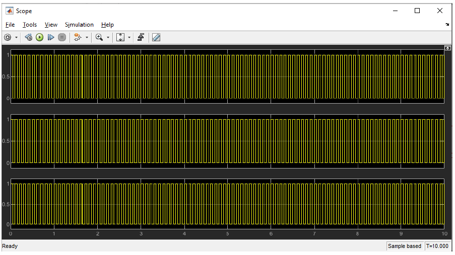
When the simulation starts running, double-click to open the Scope. This simulation runs for 10 seconds.
What should be happening?
The scope plots the simulated input signals and the digital input output readings from the target hardware.
The code execution profiling report can be generated by going to SIL/PIL tab → Compare Runs → Generate Report in the Top model.