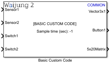
How this block appears in a Simulink model?
What can be configured?
Configuration Parameter |
Selectable Option/Value |
Description |
Mask display name |
|
Enter display name which appears on the block display. |
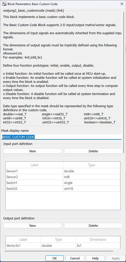
Input port definition |
|
Use the table to define data type and port label of input port(s). Leave empty if NO input port is needed. Use New and Delete buttons to add/remove ports. The top port corresponds to the first row of the table. |
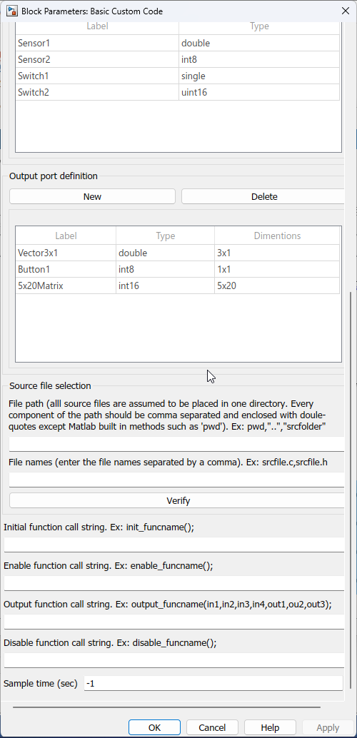
Output port definition |
|
Use the table to define data type and port label of output port(s). Leave empty if NO output port is needed. Use New and Delete buttons to add/remove ports. The top port corresponds to the first row of the table. |
File path |
|
Define the path where the files are located. Only one path can be entered and therefore, it is assumed that all files are located in the same folder. A user could either specify the relative path or the absolute path. Every component of the path should be comma separated and enclosed with double-quotes except Matlab built in methods such as pwd. Examples: •pwd,”..”,”srcfolder” •“C:”,“Users”,”admin”,”Downloads”,”srcfolder” |
File names |
|
Define the files that needs to be included in the build process. Waijung 2 will automatically copy these files to the build directory during the build process. Any number of files can be specified. Each file name has to be comma separated. |
Verify |
|
When you click this button Waijung2 will automatically check whether the specified files exist in the path specified and provide feedback. |
Initial function call string |
|
Custom function call once MCU startup. |
Enable function call string |
|
Custom function call when the Block is enabled. |
Output function call string |
|
Custom function call when the Block is executed in the model step function. |
Disable function call string |
|
Custom function call script for when the block is disabled. |
Sample time (sec) |
-1 for inherited or specify |
Enter sample time. |
When to use this block?
This block can be used when you want to add your own custom C code to the system.
How does this block work?
To use the Basic Custom Code Block you need to complete the following steps.
oStep 1: Define input/output ports for the Block.
The number of ports equals the number of elements defined in the Input port definition and Output port definition tables. The top port corresponds to the first row of the corresponding table. Leave the respective table empty if ports are not required. Supported signal data types are:
a.double
b.single
c.uint32
d.int32
e.uint16
f.int16
g.uint8
h.int8
i.boolean
Input and Output signals can be either scalar, vector, or 2-D matrix type. The dimensions of input signals are automatically inherited from the supplied input signals. The dimensions of output signals must be implicitly defined using the following format;
nRowsxnCols
For example: 4x5,3x1.
oStep 2: Define include and source files for the custom code.
Use File path edit box to define the path where the files are located. Only one path can be entered and therefore, it is assumed that all files are located in the same folder. A user could either specify the relative path or the absolute path. Every component of the path should be comma separated and enclosed with double-quotes except Matlab built in methods such as pwd.
For example: a) pwd,”..”,”srcfolder”
b) “C:”,“Users”,”admin”,”Downloads”,”srcfolder”
Use File names edit box to define the files that needs to be included in the build process. Waijung 2 will automatically copy these files to the build directory during the build process. Any number of files can be specified. Each file name has to be comma separated.
oStep 3: Define four-function prototypes: initial, enable, output, disable.
When generating code for a Simulink block, Matlab creates these four different functions. Among them, only the output function is mandatory as that is responsible for updating the output port signals of the block.
▪Initial function
An initial function will be called once at MCU start-up.
▪Enable function
An enable function will be called at system initialization and every time the block is enabled, e.g. in a case where a block is located in an Enabled Subsystem.
▪Output function
An output function will be called every time step to compute output values.
▪Disable function
A disable function will be called at system termination and every time the block is disabled, e.g. in a case where a block is located in an Enabled Subsystem.
Your job is to define function prototypes that will be wrapped inside these automatically-generated MATLAB function calls. The function definitions of the prototypes specified are to be found in the included source and header files. Apart from the main function prototype, additional C code lines can also be specified if necessary in each of the edit box spaces mentioned below.
▪The Initial function can be defined in the Initial function call string edit box. The Initial function must not have any parameters.
▪The Enable function can be defined in the Enable function call string edit box.
▪The Disable function can be defined in the Disable function call string edit box.
▪The Enable function and Disable function must not have any parameters. These functions will be called every time the system is initialized/terminated and enabled/disabled.
▪The Output function can be defined in the Output function call string edit box. The Output function requires input and output (scalar) signals (from input/output ports of the block) to be declared as parameters of the output function. The parameters for the custom code output function must follow the following requirements.
oAlways start with input (if any) and follow by output (if any).
oUse in### and out### for input and output signal respectively, where ### represent digits starting from 1.
For example:
i.The block has 2 inputs and 3 outputs, output function prototype is void custom_output_function_name(in1,in2,out1,out2,out3);
ii.The block has 0 inputs and 3 outputs, output function prototype is void custom_output_function_name(out1,out2,out3);
iii.The block has 2 inputs and 0 outputs, output function prototype is void custom_output_function_name(in1,in2);
When designing the custom C library, it is important to add the header rtwtypes.h where the Matlab typedefs are defined. These typedefs must be used when developing the custom C library functions.
Data type specified in the mask |
Corresponding type definition |
double |
real_T |
single |
real32_T |
int8 |
int8_T |
uint8 |
uint8_T |
int16 |
int16_T |
uint16 |
uint16_T |
int32 |
int32_T |
unt32 |
unt32_T |
boolean |
boolean_T |
Demo
Demo file : esp32_basic_customcode_demo.slx
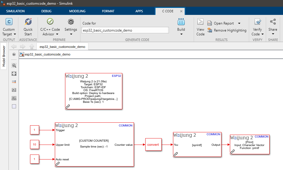
Description
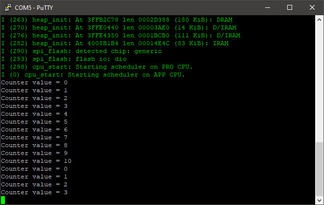
In this example, a custom counter block has been implemented using the Basic Custom Code Block. To observe the counter value, the output of the block is connected to a Print block via a String Processing block.
Setup
First, download the basic_customcode_demo_lib.zip and extract the content. Copy the extracted folder to the same folder as the model file. Open the model file from Matlab.
A serial monitor software application is required to get the expected results. For this example, PuTTY open-source SSH and telnet client is used to monitor the serial output.
What should be happening?
After the model file is compiled and uploaded to the ESP32 board, open the PuTTY software and connect to the relevant serial port with a baud rate of 115200. The following output should be visible on the serial monitor software.