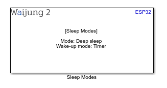
How do these blocks appear in a Simulink model?
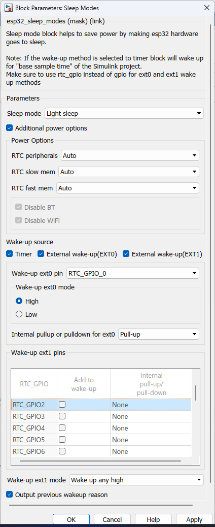
What can be configured?
Configuration Parameter |
Selectable Option/Value |
Description |
Sleep mode |
Light sleep--Deep sleep |
Select sleep mode |
Additional power option |
Check--Uncheck |
Enable additional power option for the user to control |
RTC peripherals |
Auto-On-Off |
Set power to RTC peripherals. This will override if ext0 or ext1 is selected |
RTC slow mem |
Auto-On-Off |
Set power to RTC slow memory |
RTC fast mem |
Auto-On-Off |
Set power to RTC fast memory |
Disable BT |
Check--Uncheck |
Select to disable BT by calling these functions esp_bluedroid_disable(), esp_bt_controller_disable() BT connections will not be maintained in deep sleep or light sleep modes |
Disable WiFi |
Check--Uncheck |
Select to disable WiFI by calling esp_wifi_stop() function WiFi connections will not be maintained in deep sleep or light sleep modes |
Timer |
Check--Uncheck |
Select timer as a wake-up source. Wake-up timer will be the base time of the Simulink model. |
External wake-up(EXT0) |
Check--Uncheck |
Select ext0 as a wake-up source. Set of configuration parameters will open to set up this. |
External wake-up(EXT1) |
Check--Uncheck |
Select ext1 as a wake-up source. Set of configuration parameters will open to set up this. |
Wake-up ext0 pin |
RTC_GPIO_0 to RTC_GPIO_17 for ESP32 RTC_GPIO_0 to RTC_GPIO_21 for ESP32S2 & ESP32S3 |
Select ext0 wake-up pin. esp32 - https://docs.espressif.com/projects/esp-idf/en/latest/esp32/api-reference/peripherals/gpio.html esp32s2 - https://docs.espressif.com/projects/esp-idf/en/latest/esp32s2/api-reference/peripherals/gpio.html esp32s3 - https://docs.espressif.com/projects/esp-idf/en/latest/esp32s3/api-reference/peripherals/gpio.html |
Wake-up ext0 mode |
High--Low |
Input level which will trigger the wakeup |
Internal pullup or pulldown for ext0 |
None--Pull-up--Pull-down |
Select internal pullup or pulldown for the ext0 pin. If "None" is selected external pullup or pull down need to be set. |
Wake-up ext1 pins |
|
Can select multiple pins to trigger wakeup from ext1. Use table to select pins and internal pullup/pulldown for the respective ext1 pin. |
Wake-up ext1 mode |
Wake up any high--Wake up all low |
Select logic function used to determine wakeup condition Wake up any high - wake up when any of the selected pins are high Wake up all low - wake up when all selected GPIOs are low |
Output previous wakeup reason |
Check--Uncheck |
Output wakeup reason from a port |
INPUT/ OUTPUT Port
Port Name |
Port Type |
Date Type |
Range |
Description |
wakeup reason |
Scalar |
uint8 |
Expected values 0 or 12 |
Wakeup reason to the respective number can be found in here |
When to use this block?
This block implements sleep modes to save some power in some applications.
How does this block work?
Using this block will allow the user to put the esp32 to a given sleep mode such that the power consumption of the chip will drastically goes down. Make sure either one of the wake-up modes is enabled otherwise it won't go to sleep.
Description
Light sleep mode, digital peripherals, most of the RAM, and CPUs are clock-gated, and supply voltage is reduced. Upon exit from light sleep, peripherals and CPUs resume operation, their internal state is preserved.
Deep sleep mode, CPUs, most of the RAM, and all the digital peripherals which are clocked from APB_CLK are powered off. The only parts of the chip which can still be powered on are:
•RTC controller
•RTC peripherals
•ULP coprocessor
•RTC fast memory
•RTC slow memory
Note: In deep sleep and light sleep modes, wireless peripherals are powered down
If the wake-up method is selected to timer it will wake up for "base sample time" of the Simulink project. Deep sleep mode chip will acts as a reboot when it wake-up from sleep. Variables in the Simulink model might reset due to this situation.
Find respective RTC_GPIO pin number to GPIO pin
Demo
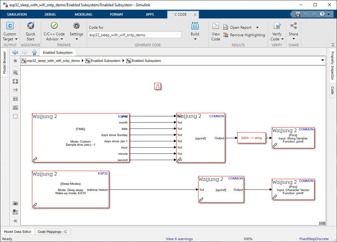
Demo file : esp32_sleep_with_wifi_sntp_demo.slx
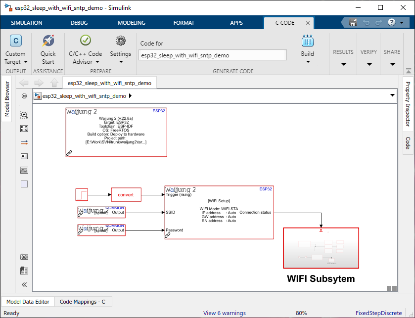
WIFI Subsytem:
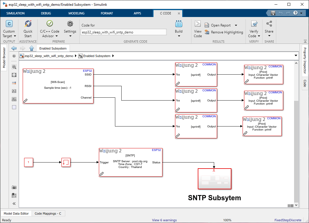
SNTP Subsystem:
Description
This example shows how to use the Sleep Mode block with a Simulink project.
What should be happening?
Once WiFi is connected it will give the connection info by the serial monitor(baud rate - 115200). Next, it will try to synchronize the time from the sntp block. Once it has been synchronized it will output the time for the serial monitor and go to deep sleep mode. Sleep Mode block is set to ext0 as the wake-up mode so until the RTC_GPIO pin is triggered high this will stay sleep. If the wake-up signal is triggered It will do the previous steps as mentioned.
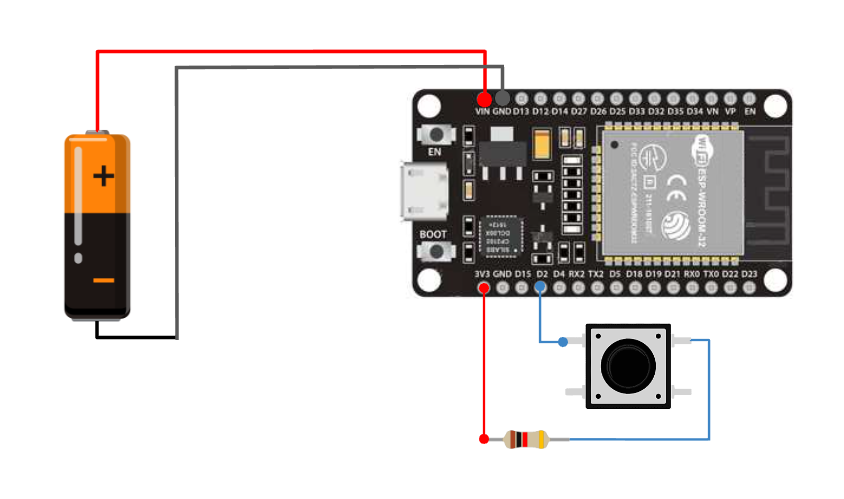
Hardware Setup
1. ESP32
2. Resistor(~1k)
3. Push button