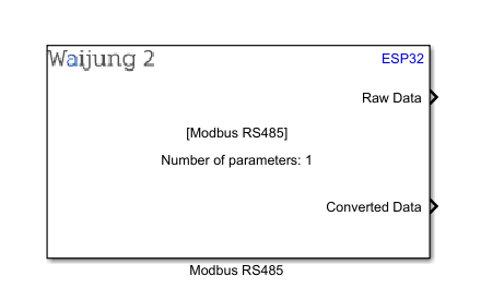
How this block appears in a Simulink model?
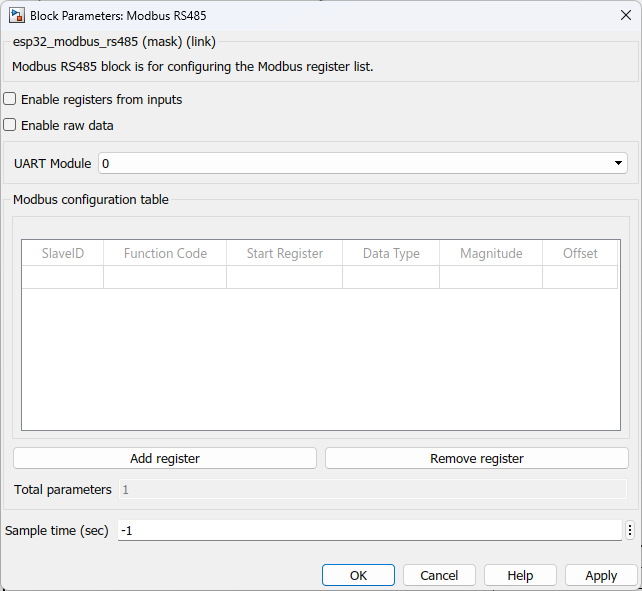
What can be configured?
Configuration Parameter |
Selectable Option/Value |
Description |
Enable registers from inputs |
Check--Uncheck |
Enable parameters from input ports.Default uncheck. |
Enable raw data |
Check--Uncheck |
Enable raw data from input ports.Default uncheck. |
UART Module |
0--1--2 |
UART port number which used for RS485 |
SlaveID |
|
unique identifier assigned to a slave device on a Modbus network |
Function code |
3 |
Code that specifies the type of Modbus function to be performed by a Modbus message. Function code 3: Read Holding Registers (used to read the contents of holding registers in a Modbus slave device) |
Start register |
|
Starting address of a block of data within a Modbus slave device |
Data type |
int8--uint8--int16--uint16--int32 inverse--uint32 inverse--int32--uint32--float inverse--float--int64 inverse--uint64 inverse--int64--uint64--double inverse--double |
Represent the different types of data that can be stored in Modbus holding registers |
Magnitude |
|
In some Modbus devices, the values stored in the registers are not in the format or range that is needed by the application reading the data. In these cases, a multiplier and/or offset value may be applied to the Modbus register reading to convert it to a format or range that is more useful for the application |
Offset |
|
An offset value may also be added to the Modbus register reading to shift the range of the data |
Add register |
|
Add a new row to the table |
Remove register |
|
Remove selected row from the table |
OUTPUT Port
Port Name |
Port Type |
Date Type |
Description |
Raw data |
Vector |
single |
The port outputs a vector with the raw data which request from slave device |
Converted data |
Vector |
single |
The port outputs a vector with the converted data which request from slave device |
When to use this block?
This block is use to configure Modbus registers. When using this block, ESP hardware works as a Modbus 'master' in the Modbus network. The master device is responsible for initiating and controlling communication with one or more "slave" devices. The master device sends requests to the slave devices to read or write data, and the slave devices respond with the requested data or an error message if an error occurs.
The Modbus master device typically sends requests to the slave devices using Modbus function codes. These function codes specify the type of Modbus request being sent, such as a request to read a holding register or write a coil.The master device also typically specifies the slave device ID in its requests to indicate which slave device the request is intended for. This allows multiple slave devices to be connected to the same Modbus network and ensures that each request is sent to the intended device.
In addition to requesting data from slave devices, a Modbus master device may also write data to slave devices. For example, the master device may send a request to write a value to a holding register on a slave device.Overall, the Modbus master device is responsible for managing the communication between multiple slave devices and the application that is using the Modbus network.
How does this block work?
•Modbus RS485: Use to set configure slave Modbus registers.
Demo
Demo1 file : esp32_modbus_rs485_demo1
Demo2 file : esp32_modbus_rs485_demo2
Demo1
Description
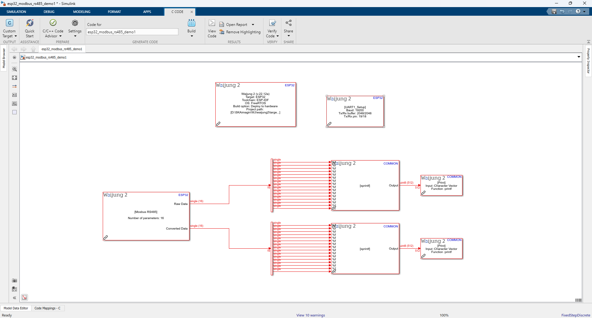
This example demonstrates how to use Modbus RS485 block in a real application. When using this block ESP hardware works as a 'Modbus Master' device on the network. Master device is responsible for initiating and controlling communication with one or more devices. This example communicates with one Modbus slave device and it sends requests to the slave device to read or write data and the slave device responds with the requested data or an error message if an error occurs.
Full Model
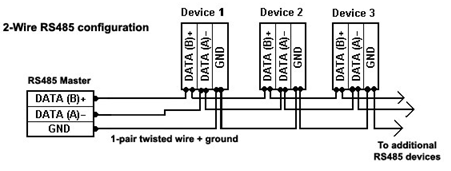
Hardware setup
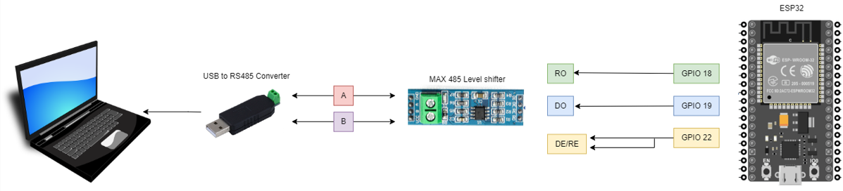
Description
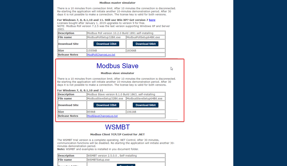
For the demonstration, we use Modbus slave simulator software by www.modbustools.com and you can download it from https://www.modbustools.com/download.html.Please note this software is not free but 30 days trial version is available to users.
Before build the project, you have to configure the slave simulator software as below steps.
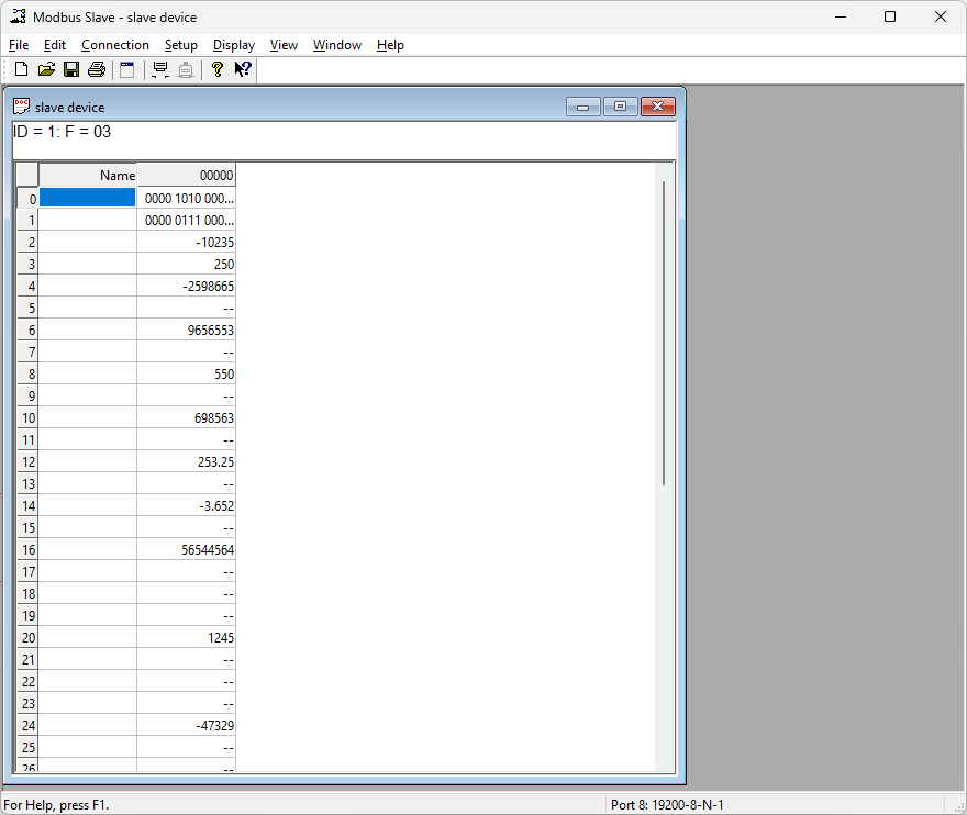
Modbus slave simulator demo file: slave device
Step 1: Before building the project, you have to configure the slave simulator software as per the below steps.
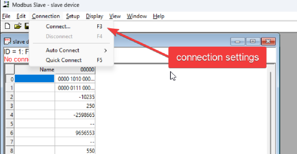
Step 2: Setup slave configuration parameters as below. Select the correct COM port of the USB to RS485 converter.
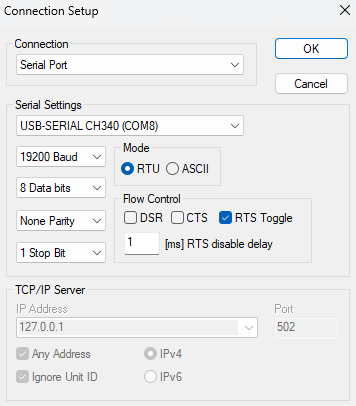
Step 3: After setting connection parameters, select OK to establish the RS485 connection. If everything is fine the slave device transmits data to the master(ESP hardware) as it requests data from the slave.
What should be happening?
Build the demo1 file and once it successfully deploys to the hardware, open serial communication software to test the demo. Select the correct COM port in the software to monitor the data. As in the below image, you can see receiving data from the slaves to the master.
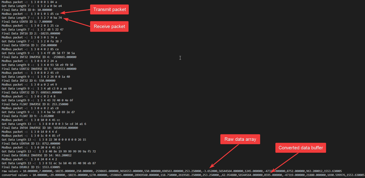
Block output ports give raw and converted data as a string vector array as shown in the image. For the converted values applies the y = mx + c equation. 'm' and 'c' are the magnitude and offset values respectively and 'x' is the raw value which receive from the slave.
Demo2 : Same as demo1 but use input ports to configuration
Full Model
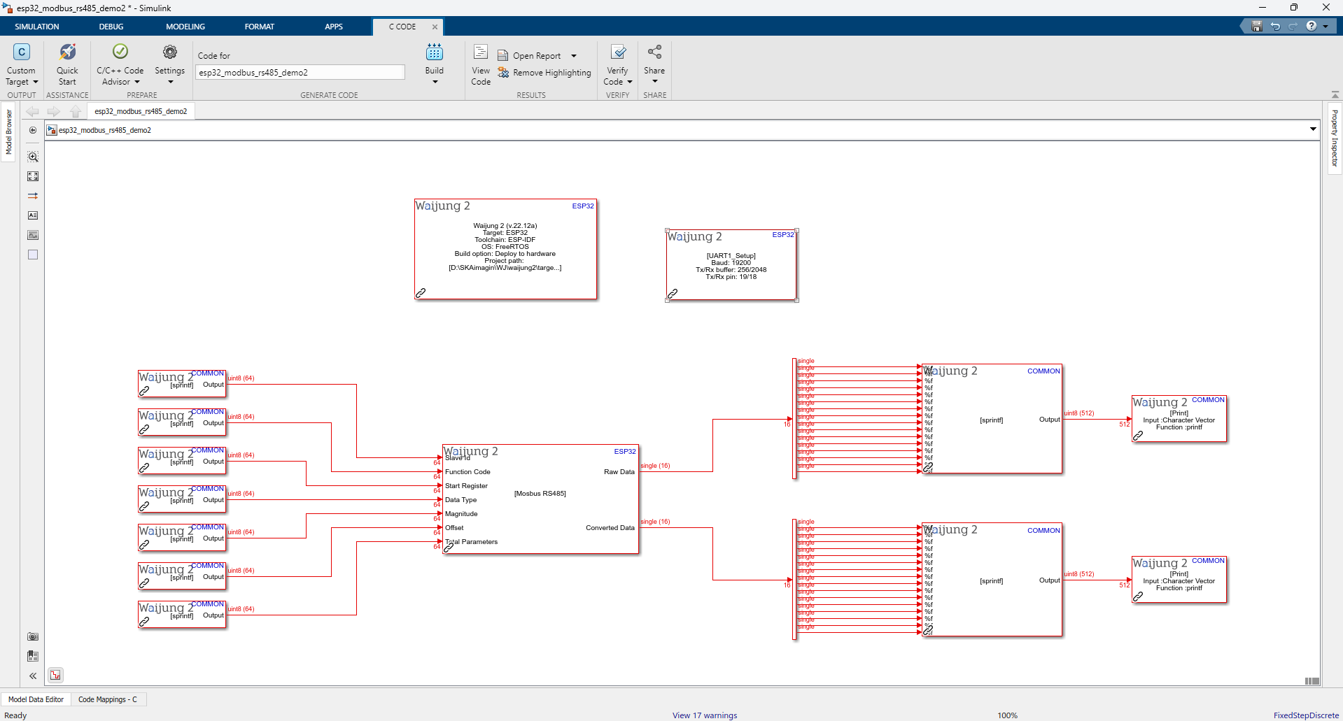
Description
This demo is the same as demo1 but it uses input ports to configure the Modbus register list. A string processing block is used for each register setting and it uses to pass settings as an input array. For ''Data type" it passes a string array specifying a number instead of a data type name. The respective data type of the number is as below list.
•0 - int8
•1 - uint8
•2 - int16
•3 - uint16
•4 - int32 inverse (Big-endian)
•5 - uint32 inverse (Big-endian)
•6 - int32 (Little-endian byte swap)
•7 - uint32 (Little-endian byte swap)
•8 - float inverse (Big-endian)
•9 - float (Little-endian byte swap)
•10 - int64 inverse (Big-endian)
•11 - uint64 inverse (Big-endian)
•12 - int64 (Little-endian byte swap)
•13 - uint64 (Little-endian byte swap)
•14 - double inverse (Big-endian)
•15 - double (Little-endian byte swap)