Developing the balancing algorithm
In this section of the tutorial, we will delve into the development of a balancing algorithm that is pivotal for the self-balancing robot’s stability. The algorithm’s primary function is to assess the robot’s tilt angle and decide whether to engage the PID controller. Here’s how it works:
•When the tilt angle is less than 70 degrees: The algorithm activates the PID controller, which then calculates the appropriate PWM (Pulse Width Modulation) output. This output is applied uniformly to both wheels, enabling the robot to adjust its balance accordingly.
•When the tilt angle exceeds 70 degrees: The robot is considered to be at risk of falling. In response, the algorithm sets the integrals of the PID controller and the PWM output to zero, effectively halting any further wheel movement. Additionally, the encoder is reset to prepare for the next balancing attempt.
This mechanism ensures that the robot only attempts to balance itself when the angle is within a manageable range, thereby preventing unnecessary movements that could lead to falls or instability.
Example Simulink Model: br_balancing_algorithm.slx
Step 01: Add "Data Store Memory" block and Configure
Add "Data Store Memory" block. Double-click on the Data Store Memory block to open its configuration parameters. Set Data store name to "pwm_out" and change Data type to int16 in the Signal Attribute tab.

Figure 127: Add Data Store Memory block as pwm_out

Figure 128: Set data type to int16
Step 02: Add "if" block and Configure
Add "if" block. Double-click on the if block to open its configuration parameters. Set if expressions to "u1 < 70" and tick the show else condition check box.

Figure 129: Set If expression
Step 03: Create Balancing Algorithm Subsystem
Select the PID controller as follow and create a subsystem by right-clicking.

Figure 130: Create Subsystem
Step 04: Add If Action Subsystem
Add Action port block and connect it to the 'else' on the If block. Copy the Action Port block inside If Action Subsystem and paste it inside Balance Algorithm Subsystem. Also connect the output of PID controller to pwm_out value using Data Store Write block.
Lastly connect the if block to the Balance algorithm subsystem.

Figure 131: Add Action block and write data to pwm_out
Step 05: Reset when robot angle > 70
Set the value of integrals of PID controlers and pwm_out to zero. Also reset the encoder by assigning 0x00 hex value.

Figure 132: Set Integrals and pwm_out to zero

Figure 133: Reset Encoder
Step 06: Set the Wheel Speed
Add Data Store Read block to access the pwm_out value and assign it to both wheels.

Figure 134: Set wheel speed

Figure 135: Balancing Algorithm Simulink model
Tuning the PID Controller
In this section, we will explore the process of real-time tuning for the PID controllers of our self-balancing robot. Utilizing the external mode option with Wi-Fi stationary mode (wireless) in Waijung2, we can adjust the PID parameters on-the-fly and observe the effects immediately. This approach allows for a more intuitive and efficient tuning process. We have two distinct PID controllers to tune: one for the angle and one for the speed of the robot. Each controller has three parameters—Kp, Ki, and Kd—making a total of six tuning parameters.
Step 01: Add Knobs and Configure
Add Six Knob blocks for each PID component. Double-click on the knob block to open its configuration parameters. Link the the corresponding constant block to each knob and adjust reasonable values for the Max and Min values.

Figure 136: Configure Knobs

Figure 137: Simulink model with tuning knobs
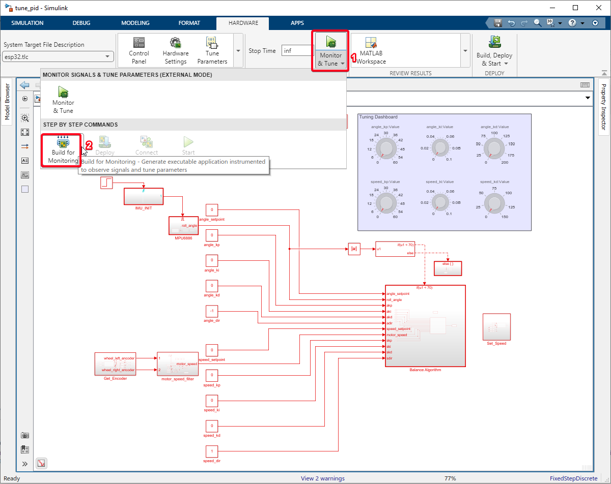
Step 02: Build Simulink Model
Click on the Hardware Tab. Select the Drop down of "Monitor & Tune" and select "Build for Monitoring".
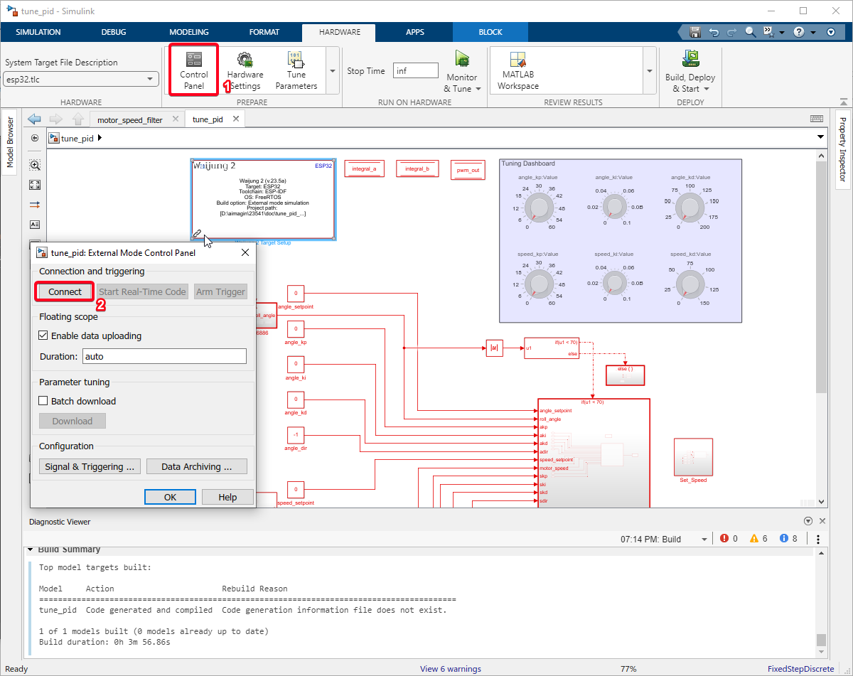
Step 03: Run External mode Simulation
Click on the Control Panel and click on the 'Connect' button.
Step 04: Tune Angle PID Controller
•Start with Kp, Ki, Kd all at zero.
•Gradually increase Kp until it stops angle oscillations.
•Add Kd to reduce settling time.
•Introduce Ki to eliminate steady-state error.
Step 05: Tune Speed PID Control
Start with kp, kd, ki at zero.
•Increase kp to get a speed response.
•Add kd for a better response without instability.
•Use ki to eliminate steady-state speed error.
Step 06: Fine-Tuning and Iteration
•Balance speed and stability.
•Record changes and observations.
•Aim for minimal oscillation, quick response, and no steady-state errors.
In this section, we’ve fine-tuned the PID controllers for our robot, starting from zero and adjusting Kp, Ki, and Kd to optimize angle and speed control. Our iterative process aimed for a balanced, responsive system with minimal oscillation and no steady-state errors. The result is a robot that balances effectively.
Example Simulink Model: br_balancing_algorithm.slx