Design overview
Waijung2 Target Setup block appearance in a Simulink model,
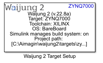
Waijung 2 Target Setup block mask overview,
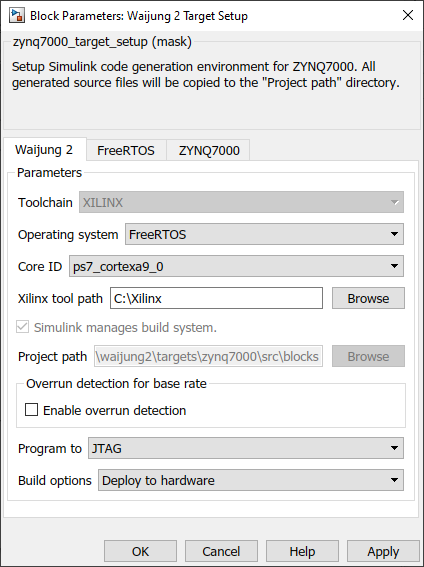
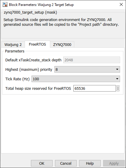
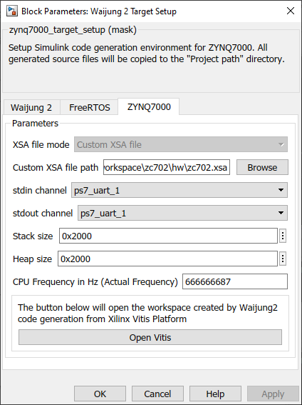
PIL simulation and External mode configuration,
Waijung 2 target setup block behavior
Waijung 2 target setup block is used to setup Simulink code generation environment for ZYNQ7000 target. It is mandatory to use this block in every model file created using Waijung 2 block set for the ZYNQ7000 target.
Waijung 2 target setup block configuration
Waijung 2 tab
Configuration Parameter |
Selectable Option/Value |
Default Value |
Description |
|||||||
Operating system |
|
BareBoard |
Select the required OS to run the application. The code generation will be done according to the OS. |
|||||||
Core ID |
|
ps7_cortexa9_0 |
Select the preferable core id to run the application |
|||||||
Xilinx tool path |
|
C:\Xilinx |
Browse the folder path to the Xilinx folder |
|||||||
Enable overrun detection |
|
Off |
Enable overrun detection of base rate. Use this option for only testing. If an overrun is detected, the application will be terminated. |
|||||||
GPIO Pin |
|
7 |
If an overrun is detected, the given GPIO pin will be logic HIGH |
|||||||
Program to |
|
JTAG |
Select the programming mode |
|||||||
Flash type |
|
qspi_single |
This option will be visible when the application is program to Flash memory. Select the flash type according to the development board. |
|||||||
Build options |
|
Deploy to hardware |
Generate code: This option is used only to generate the code. Deploy to hardware: This is used to generate the C code, compile and flash to target and deploy the application in the target. External mode simulation: Run the application with the External mode simulation Processor-in-the-loop simulation: Run the application with the PIL simulation |
FreeRTOS 2 tab
This tab will be visible when the OS is set to FreeRTOS
Configuration Parameter |
Selectable Option/Value |
Default Value |
Description |
|||
Highest (maximum) priority |
5 to 30 |
8 |
The number of task priorities that will be available. Priorities can be assigned from zero to the value set in here - 1. |
|||
Tick Rate (Hz) |
|
100 |
Number of RTOS ticks per second |
|||
Total heap size reserved for FreeRTOS |
|
65536 |
This is used to set the amount of RAM reserved for use by FreeRTOS - used when tasks, queues, semaphores and event groups are created. |
ZYNQ7000 tab
Configuration Parameter |
Selectable Option/Value |
Default Value |
Description |
||||
Custom XSA file path |
|
C:\Users\admin\workspace\zc702\hw\zc702.xsa |
Browse the file path to the hardware design file which is created using Vivado design suite. |
||||
stdin channel |
|
ps7_uart_1 |
Select the interface for stdin |
||||
stdout channel |
|
ps7_uart_1 |
Select the interface for stdout |
||||
Stack size |
|
0x2000 |
Setup the stack size for the application. These modifications will be added to the linker script of the project. |
||||
Heap size |
|
0x2000 |
Setup the heap size for the application. These modifications will be added to the linker script of the project. |
||||
CPU Frequency in Hz (Actual Frequency) |
|
666666687 |
Actual set frequency in Vivado design. This value is used only in profiling in PIL simulation. |
||||
Open Vitis |
|
|
The generated platform and application projects using Waijung 2 will be opened with Vitis IDE |
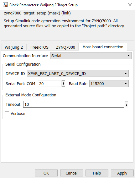
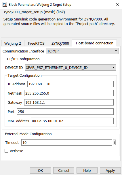
Host-board connection tab
This configurations are related to the communication interface for External mode and PIL simulation.
Configuration Parameter |
Selectable Option/Value |
Default Value |
Description |
||||
Communication Interface |
|
Serial |
Select the communication interface external mode uses to exchange data between the host and the target hardware. |
||||
DEVICE ID |
or
|
XPAR_PS7_UART_0_DEVICE_ID or XPAR_PS7_ETHERNET_0_DEVICE_ID |
Select the device ID of the driver module depends on the Communication interface as well as the Hardware reference design file (.xsa).
|
||||
Serial Port: COM |
|
20 |
Enter the ‘COM’ part to which the target is connected. |
||||
Baud Rate |
|
115200 |
Select the baud rate for serial communication. |
||||
IP Address |
|
192.168.1.10 |
Enter the IP address |
||||
Netmask |
|
255.255.255.0 |
Enter the netmask IP address |
||||
Gateway |
|
192.168.1.1 |
Enter the gateway IP address |
||||
Port |
|
256 |
Enter the network port |
||||
MAC address |
|
00-0a-35-00-01-02 |
Enter the MAC address |
||||
Timeout |
|
10 |
Timeout in seconds. |
||||
Verbose |
|
Off |
To view the external mode execution progress and updates in the Diagnostic Viewer or in the MATLAB® command window, select this check box. |