Welcome to this tutorial on implementing PID controllers on Simulink for a self-balancing robot. In this tutorial, we will be implementing two PID controllers: one for controlling the angle and the other for controlling the speed of the robot.
PID controllers, or Proportional-Integral-Derivative controllers, are widely used in control systems for their ability to minimize error and provide optimal control. They work by continuously calculating an error value as the difference between a desired setpoint and a measured process variable, and applying a correction based on proportional, integral, and derivative terms.
The PID controller we will be implementing is a single-degree-of-freedom controller, described by the transfer function:
where:
Kp is the proportional gain
Ki is the integrator gain
Kd is the derivative gain
We will be using Simulink, a block diagram environment for simulation and model-based design, to implement our PID controllers. The code for the PID controllers, which is an example from the M5stack BALA2 balancing robot, can be found in the GitHub links.
Example Simulink Model: br_pid_controller.slx
Step 01: Add & Configure Constant Blocks
Find the Constant block and add it to your model. This blocks will be used to represent the PID controller parameters:set point, Kp, Ki, Kd & direction .
Double-click on the Constant block to open its configuration parameters. Set Sample Time to -1 and change the data type to single.
Since the self-balancing robot requires control over both its angle and speed, configure two sets of ‘Constant’ blocks, one for each controller. Assign the appropriate values to these blocks that correspond to the desired behavior of your robot for maintaining balance (angle controller) and managing movement (speed controller).
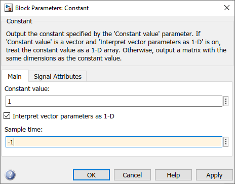
Figure 118: Configure Constant blocks
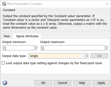
Figure 119: Configure Constant blocks
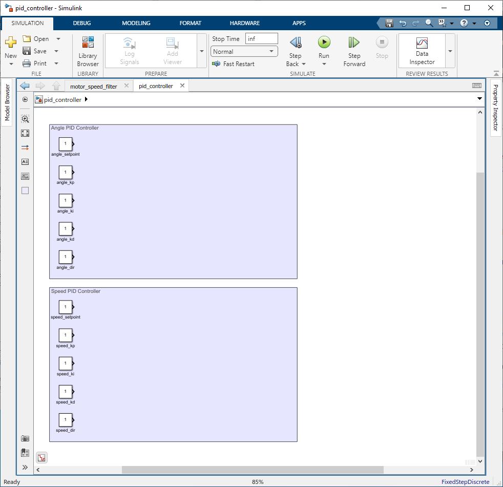
Figure 120: Add Constant blocks
Step 02: Setting Directions
The direction determines whether the controller should respond directly or inversely to the error signal. Use a ‘Abs’ block to get absolute value of the Kp, Ki, and Kd values and the use a 'Product' block to multiply with the direction.
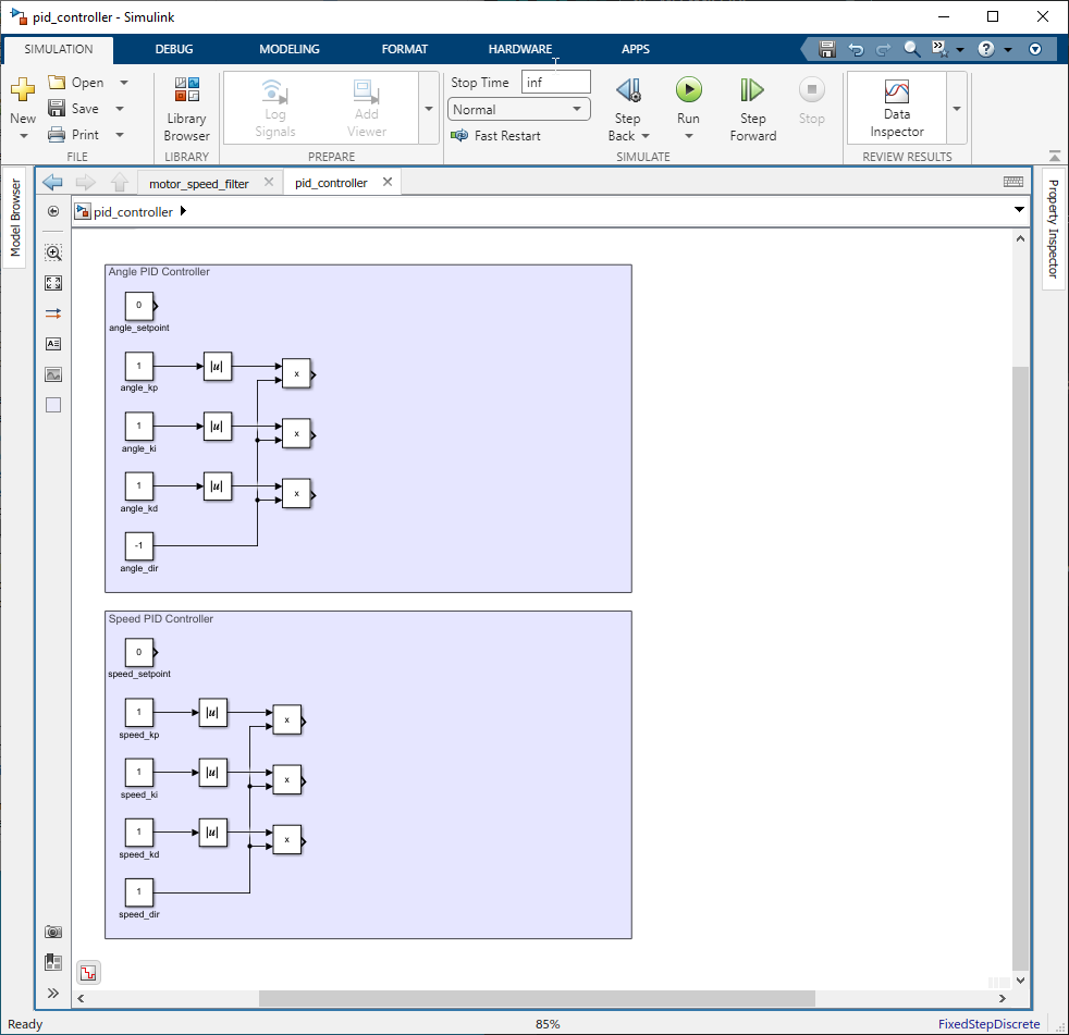
Figure 121: Set Direction
Step 03: Creating PID Equations
Construct the PID control equations using Simulink blocks. The equations are as follows:
(input will be roll angle from MPU6886 IMU for angle pid and motor speed from motor_speed_filter for speed pid)
Use ‘Sum’/'Add', ‘Data Store Memory’, 'Data Store Write', 'Data Store Read', ‘Product’, and ‘Data Type Converter’ blocks to replicate these calculations in your model.
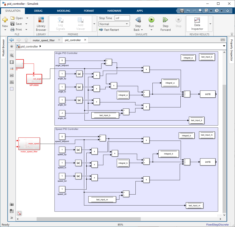
Figure 122: Create PID equations
Step 04: Setting Limits with Saturation Block
Apply constraints to the PID controller’s output to prevent excessive corrections that could destabilize the robot. Use ‘Saturation’ blocks to set the following limits:
For the angle PID:
•Integral Limits(1000,1000);
•Output Limits(1023,−1023);
For the speed PID:
•Integral Limits(40,−40);
•Output Limits(1023,−1023);
For the combined system output:
•Output Limits(1023,−1023);
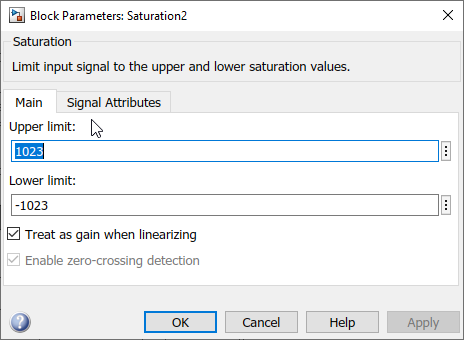
Figure 123: Configure Saturation block
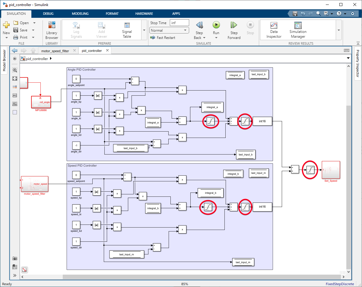
Figure 124: Setting Limits with Saturation block
Example Simulink Model: br_pid_controller.slx