In this part of the tutorial, we will focus on creating a versatile movement control algorithm that enables our self-balancing robot to execute a variety of maneuvers, including moving forward, backward, and turning left or right. To ensure that our algorithm performs well in real-world conditions, we will employ Hardware in the Loop (HIL) testing.
HIL testing is a technique used to develop and test complex real-time embedded systems. It provides an effective platform for testing the control algorithm by connecting the actual hardware components to a simulation environment. In our case, we will use Simulink’s external mode simulation to test our control algorithm in real time. This mode allows us to modify parameters on-the-fly and observe the system’s response, ensuring a dynamic and interactive testing process.
To control the robot’s movements, we will integrate push buttons within the Simulink model. These buttons will act as inputs to our control algorithm, simulating real-world commands and allowing us to direct the robot’s actions during the HIL tests. By the end of this section, we will have a robust control algorithm that can handle various movement commands and a tested system ready for deployment.
Let’s embark on this journey to bring agility and precision to our self-balancing robot’s movements.
Example Simulink Model: br_control_movement.slx
Step 01: Add & Configure Constant Blocks
Find the Constant block and add it to your model. This blocks will be used to represent the PID controller parameters:set point, Kp, Ki, Kd & direction .
Double-click on the Constant block to open its configuration parameters. Set Sample Time to -1 .
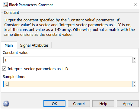
Figure 136: Configure Constant blocks
Step 01: Add two "Data Store Memory" blocks and Configure
Add two "Data Store Memory" blocks. Double-click on the Data Store Memory block to open its configuration parameters. Set Data store name to "fb" and "lr". Also change Data type to int16 in the Signal Attribute tab.
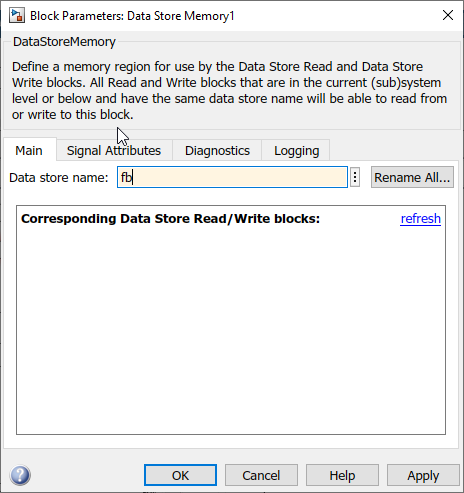
Figure 137: Set Data store name to fb
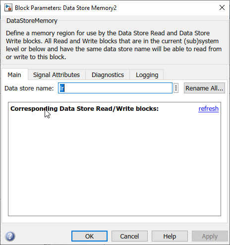
Figure 138: Set Data store name to lr
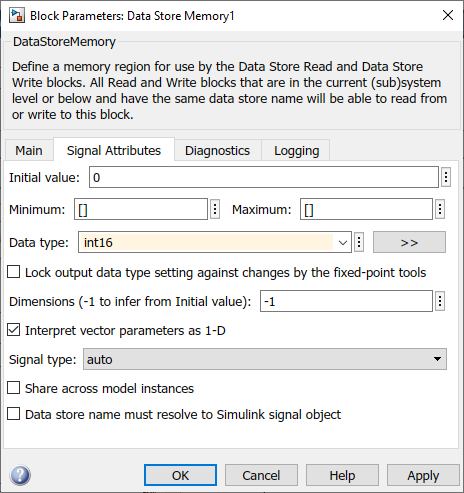
Figure 139: Change data type to int16 on both
Step 02: Add "if" block and Configure
Add four "if" blocks. Double-click on the if block to open its configuration parameters. Set if expressions to "u1 == 1" . (You can add one block with the configurations and copy paste for the remaining three.)
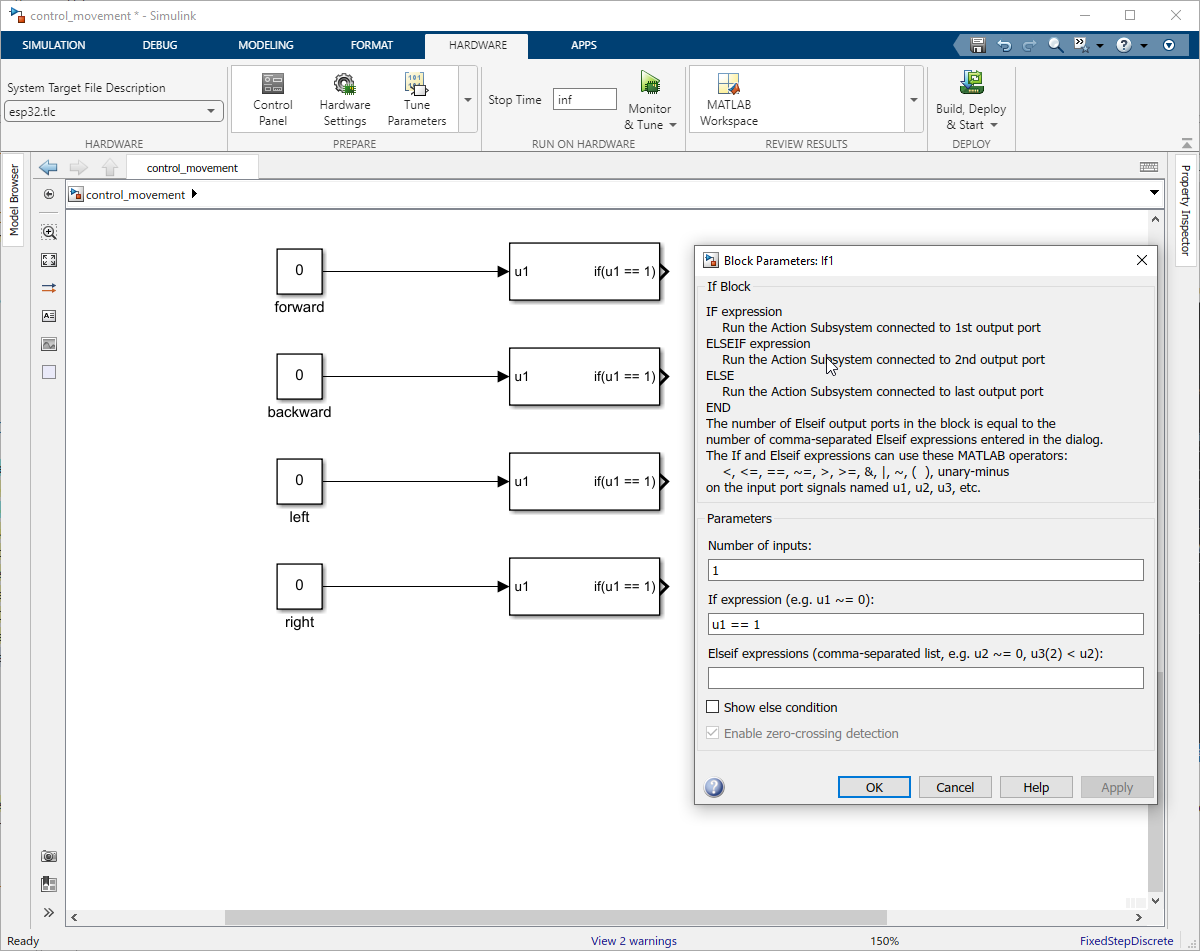
Figure 140: Add four if blocks for each direction
Add another two "if" blocks. Double-click on the if block to open its configuration parameters. Set the Number of inputs to 2. Set if expressions to "u1 == 0 & u2 ==0" .
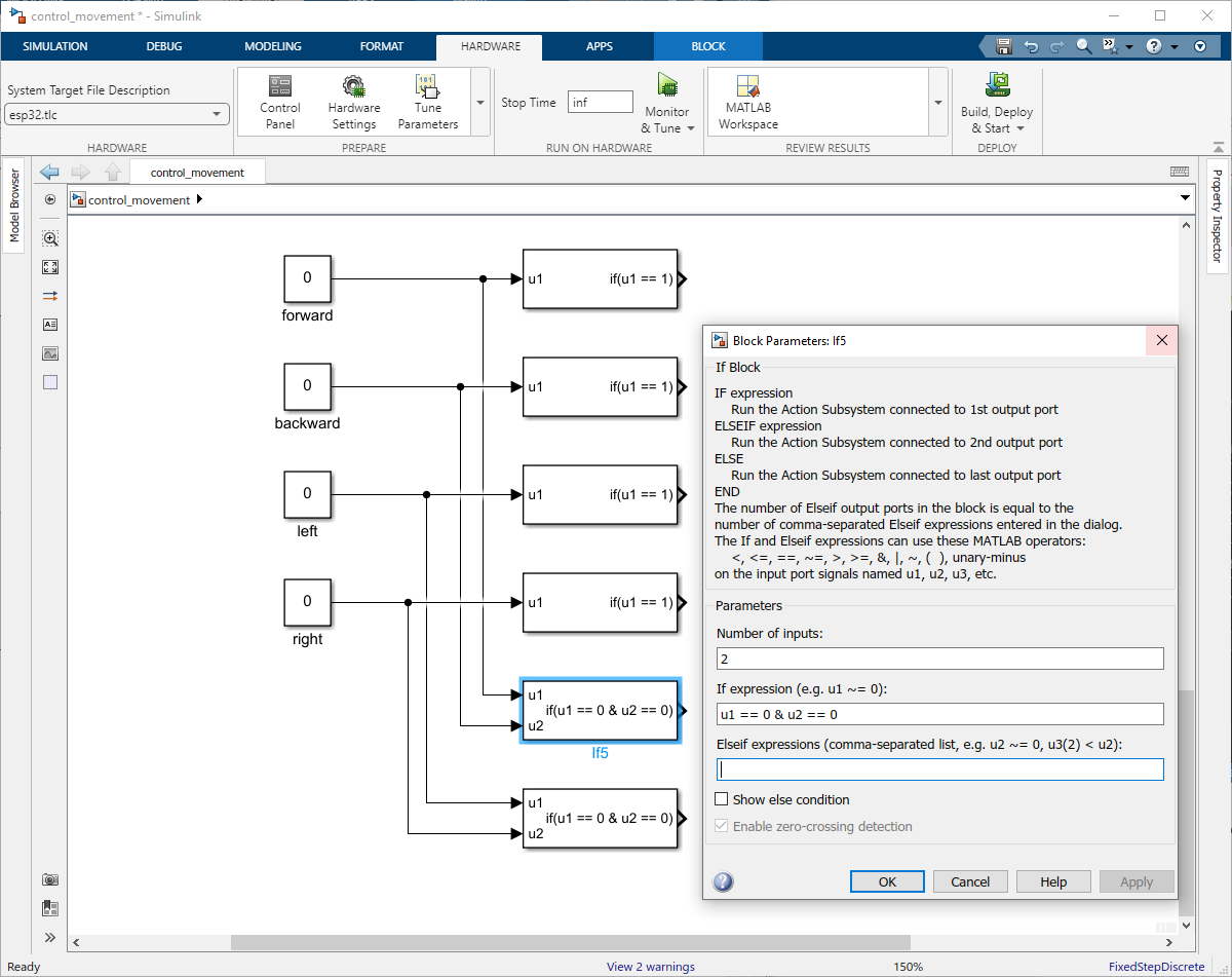
Figure 141: Add two if blocks to reset
Step 03: Add If Action Subsystem
Add six If Action Subsystem block and connect it to the each If block.
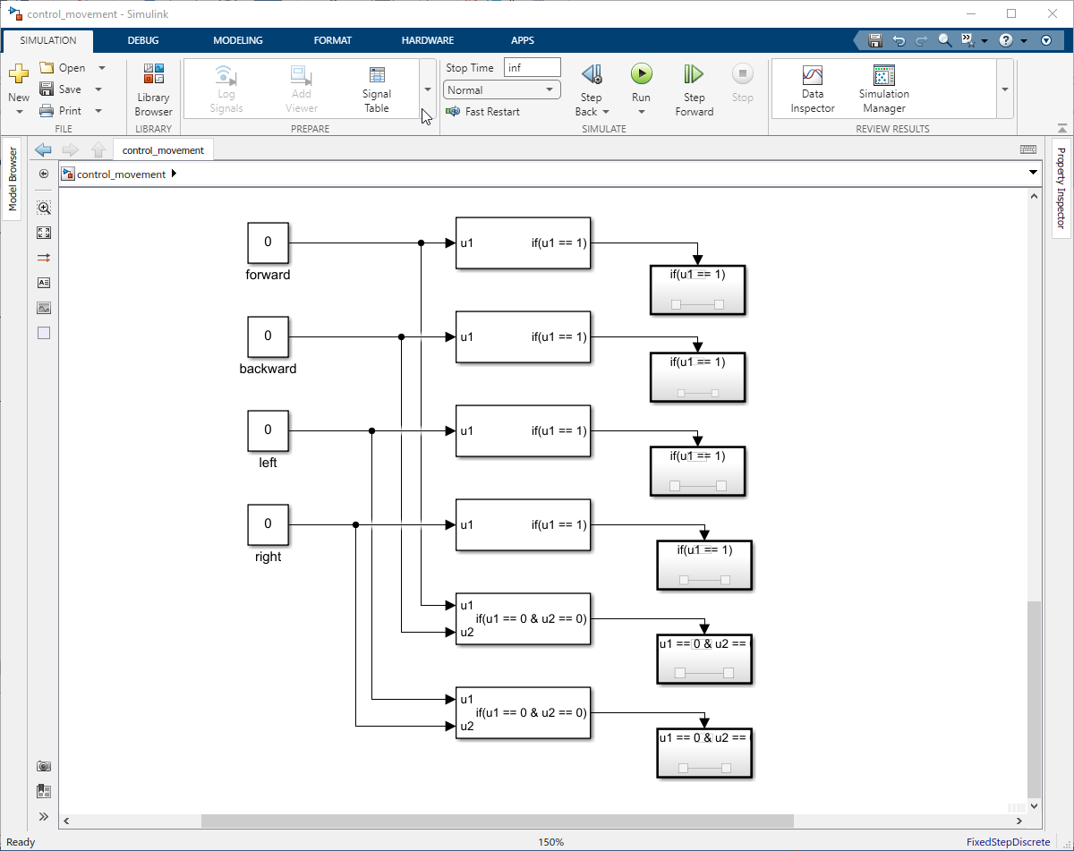
Figure 142: Add six If Action Subsystem blocks
For the first If Action Subsystem include a constant block with value 4 and -1 sample time and assigned it to the fb using Data Store write.
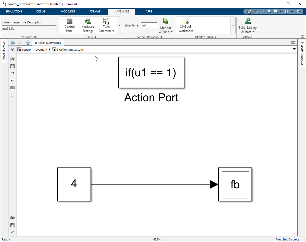
Figure 143: Move forward
For the second If Action Subsystem include a constant block with value -4 and -1 sample time and assigned it to the fb using Data Store write.
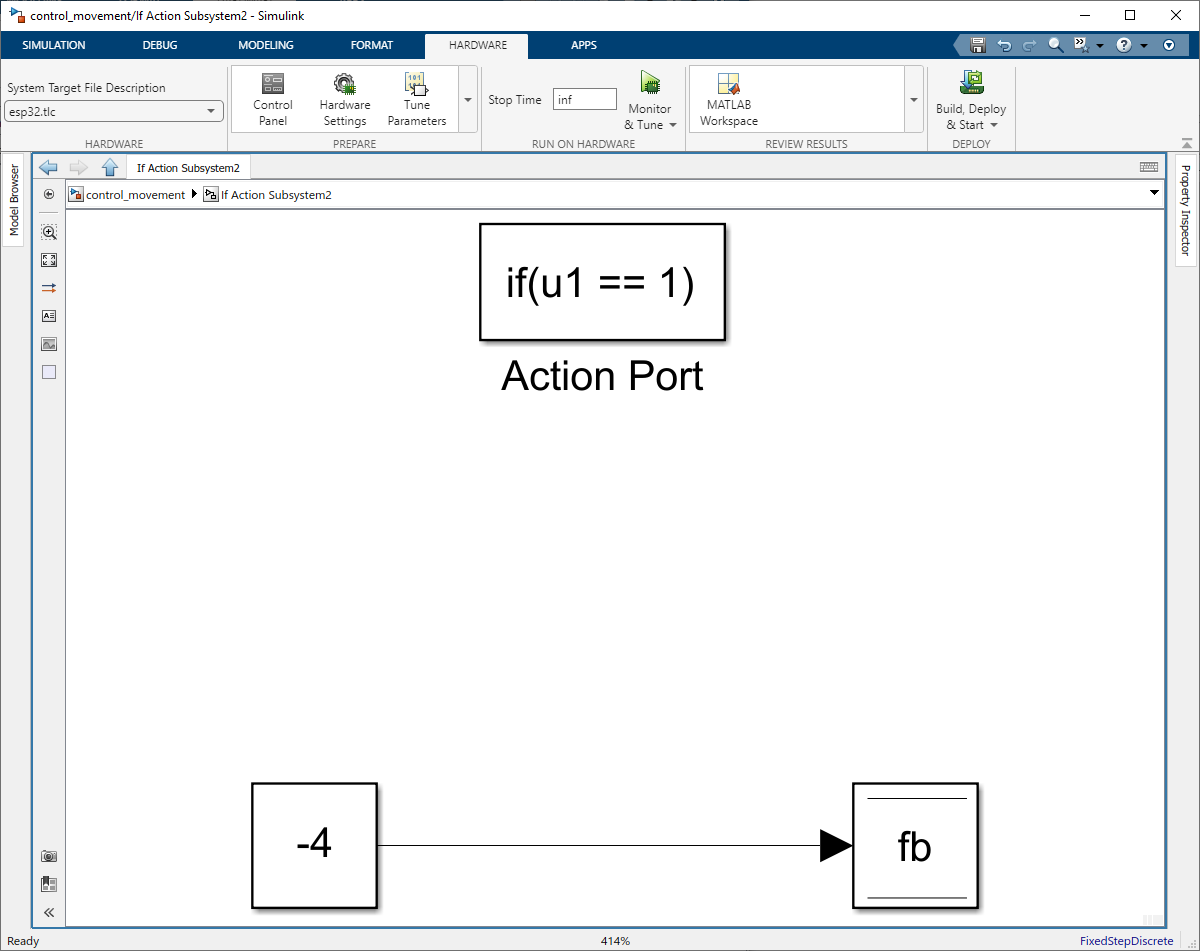
Figure 144: Move backward
For the third If Action Subsystem include a constant block with value -200 and -1 sample time and assigned it to the lr using Data Store write.
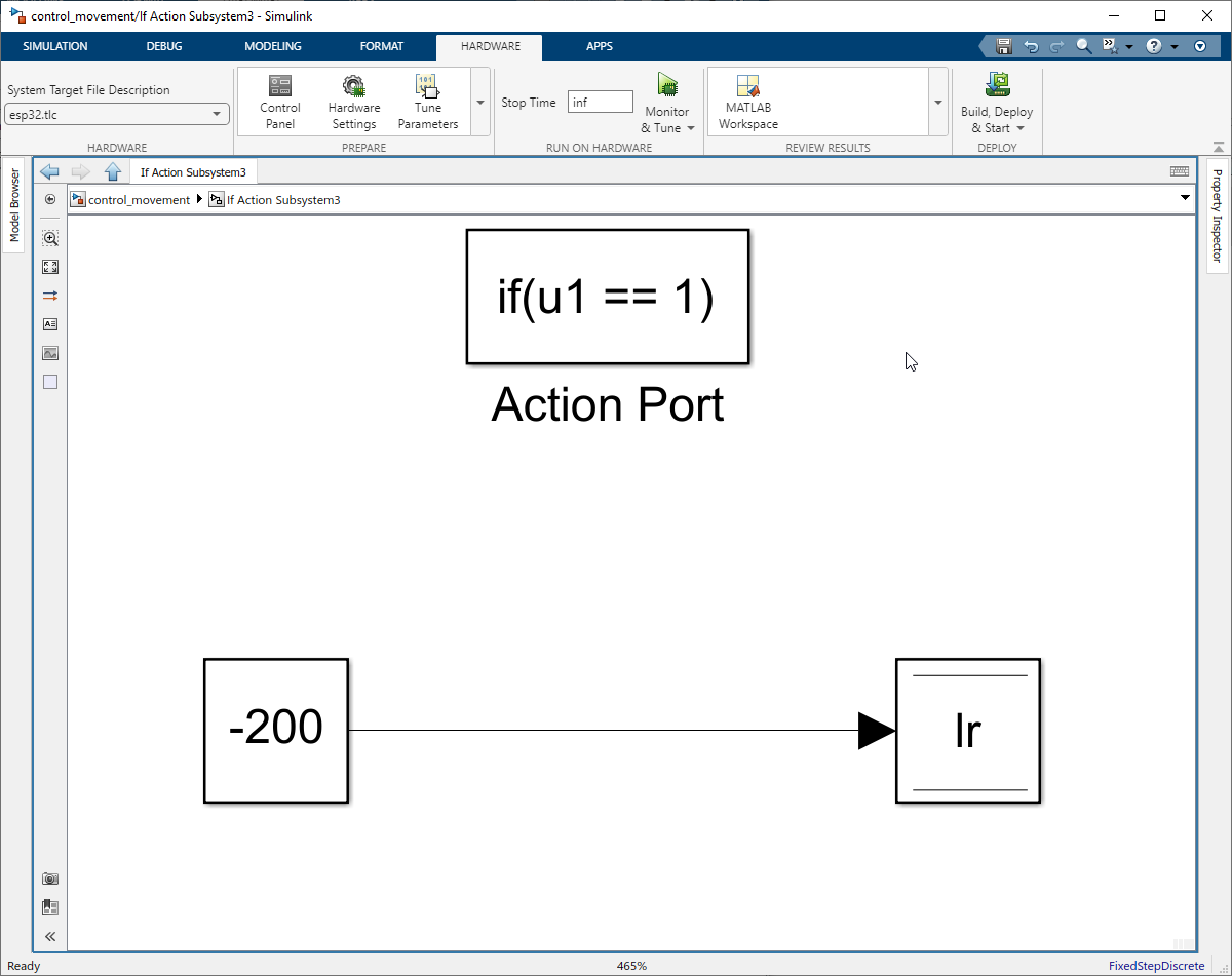
Figure 145: Turn Left
For the fourth If Action Subsystem include a constant block with value 200 and -1 sample time and assigned it to the lr using Data Store write.
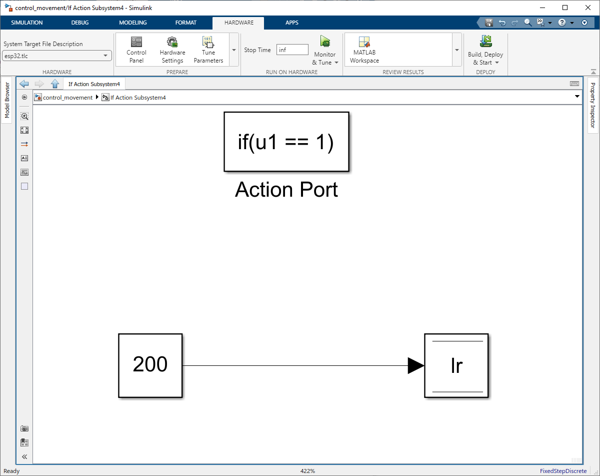
Figure 146: Turn Right
For the fifth If Action Subsystem include a constant block with value 0 and -1 sample time and assigned it to the fb using Data Store write.
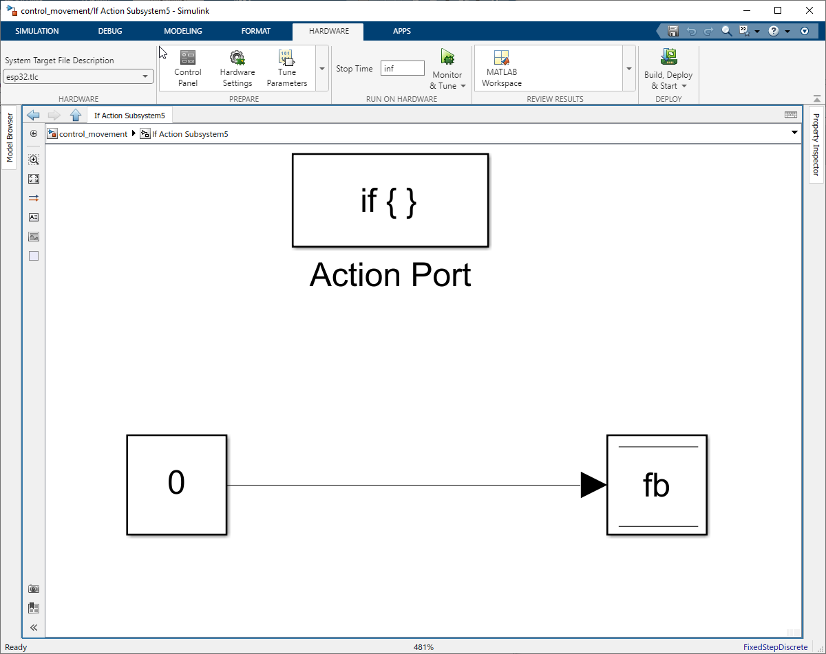
Figure 147: Stop Forward backward movement
For the sixth If Action Subsystem include a constant block with value 0 and -1 sample time and assigned it to the lr using Data Store write.

Figure 147: Stop Left and Right movement
Step 04: Add and connect Push buttons to constant blocks.
Add the four push buttons to the Simulink and link them to corresponding constant block.
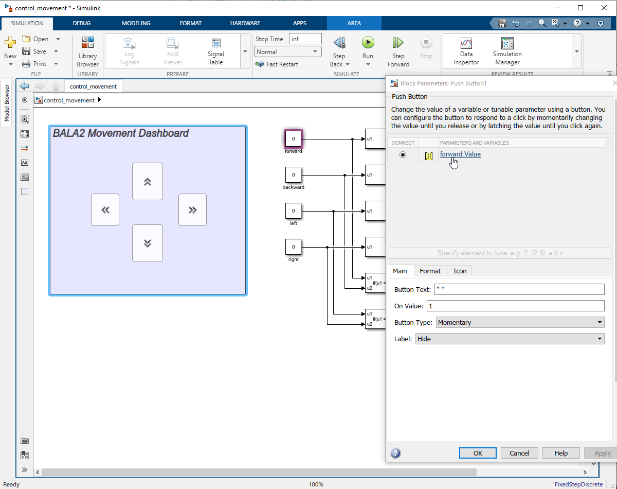
Figure 148: Add Push Buttons
Step 05: Move forward and backward mechanism
To control the robot’s forward and backward movements, we adjust the setpoint of the angle PID controller. Here’s how it works:
Forward Movement:
•Pressing the forward push button in the Simulink model sets the “fb” data store memory to +4.
•This action changes the angle setpoint to +4 degrees, prompting the robot to move forward to achieve this new angle.
Backward Movement:
•Pressing the backward push button assigns the “fb” data store memory to -4.
•The angle setpoint is now -4 degrees, causing the robot to move backward to reach the set angle.
By modifying the angle setpoint through the “fb” data store memory, we effectively command the robot to move in the desired direction while maintaining balance.
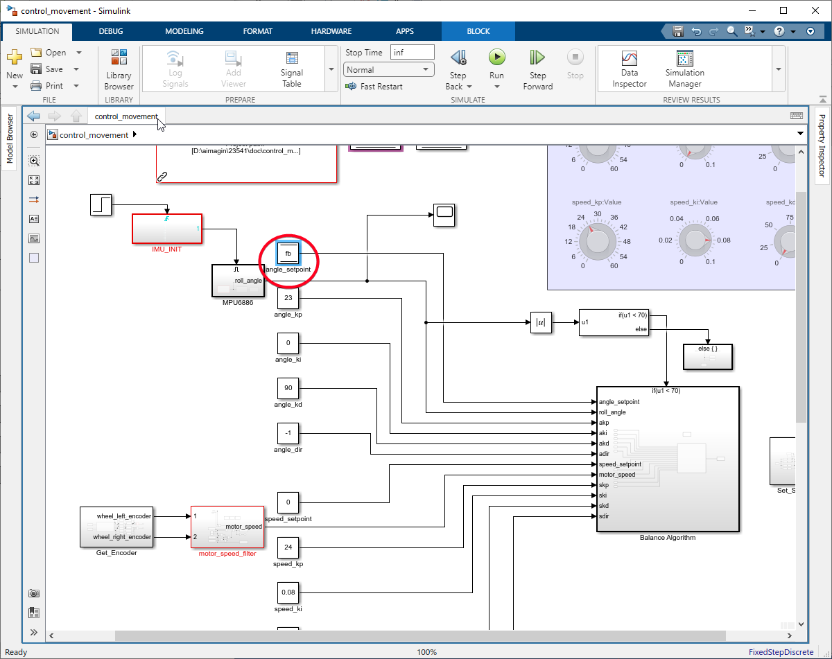
Figure 149: Forward & backward movement
Step 06: Right and Left Turn Mechanism
To facilitate the robot’s turning, we adjust the speed of each wheel by altering the lr data store memory:
Turning Left:
•Set the lr data store memory to -200.
•The PWM output from the PID controller, pwm_out, is modified by adding lr for the right wheel and subtracting lr for the left wheel.
Turning Right:
•Set the lr data store memory to +200.
•Similarly, pwm_out is adjusted by adding lr to the left wheel’s speed and subtracting it from the right wheel’s speed.
This method allows differential wheel speeds, enabling the robot to turn while maintaining balance. Use Data Store Read block to access the lr value.
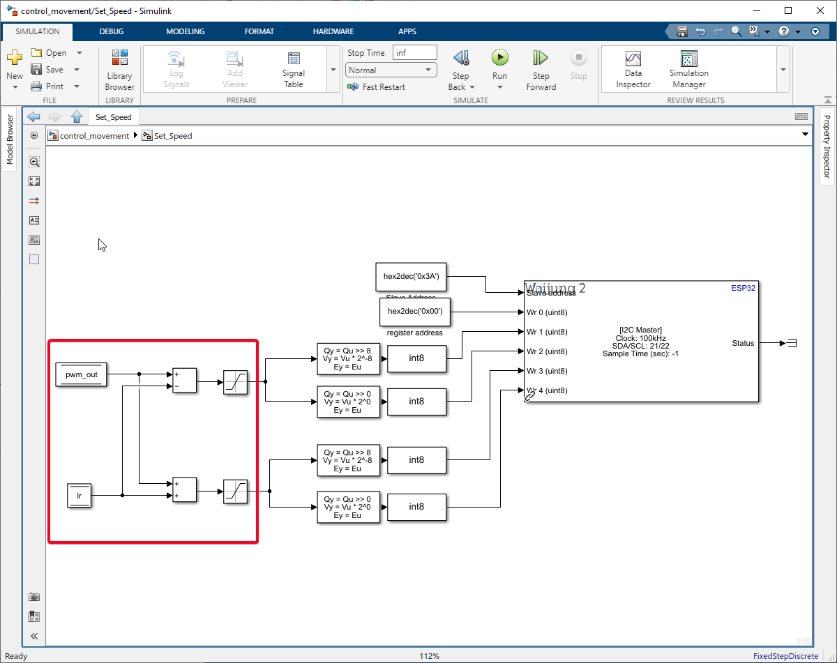
Figure 150: Right and Left Turn Mechanism
Example Simulink Model: br_control_movement.slx
Step 07: Build Simulink Model
Click on the Hardware Tab. Select the Drop down of "Monitor & Tune" and select "Build for Monitoring".
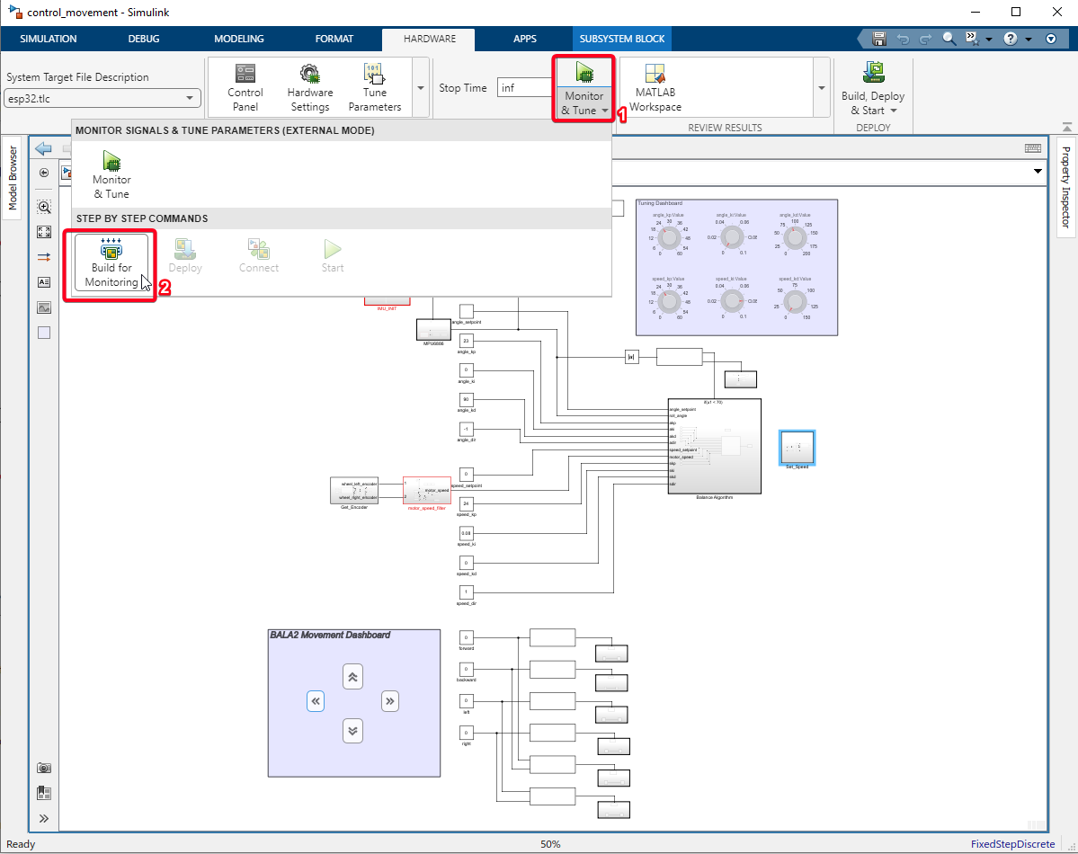
Figure 151: Build Simulink model
Step 08: Run External mode Simulation
Click on the Control Panel and click on the 'Connect' button.
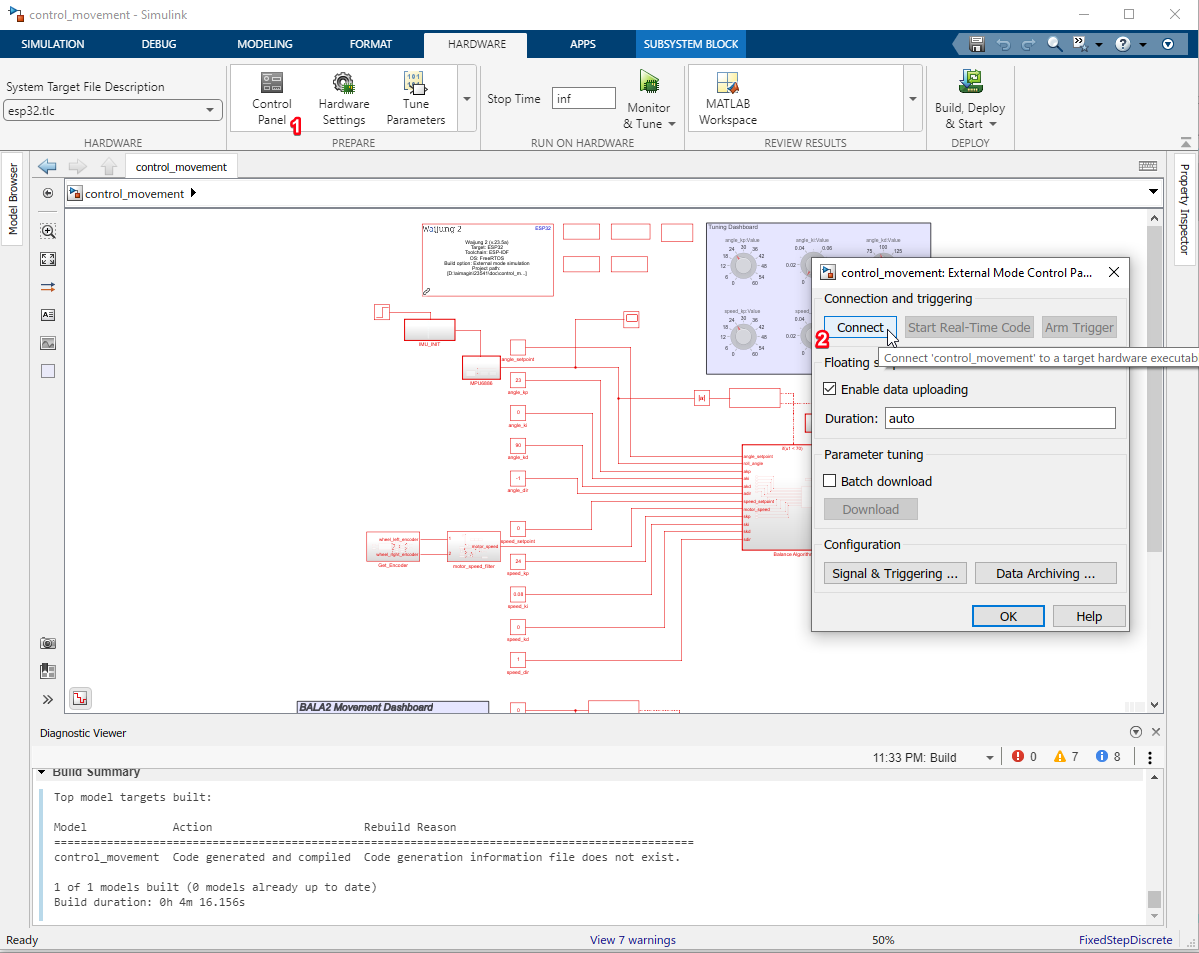
Figure 152: Run External mode simulation
Step 09: Verifying Results
•The ability to control the balancing robot’s movement wirelessly in real time is made possible by the external mode feature of the Waijung2 blockset through Wi-Fi. This feature is a key enabler in our tutorial, allowing us to demonstrate the robot’s capabilities effectively.

Figure 153: HIL with pushbuttons (GIF)