Design overview
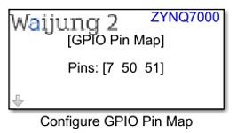
Digital GPIO Pin Map Block appearance in a Simulink model,

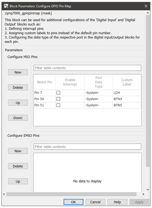
Digital GPIO Pin Map Block mask overview,

Configure GPIO Pin Map Block input interfaces
Name |
Type |
Range |
Description |
N/A |
|
|
|
Configure GPIO Pin Map Block output interfaces
Name |
Type |
Range |
Description |
N/A |
|
|
|
Configure GPIO Pin Map Block behavior
Only one block of this type can be used in a single model file. This block can be used for the following purposes:
•Assign custom labels to pins
•Assign port data types
•Specify interrupt pins
The block mask contains two tables which can be independently modified that represent MIO and EMIO pins separately.
Configure GPIO Pin Map Block configuration
Configuration Parameter |
Selectable Option/Value |
Description |
|
New |
|
Create a new entry |
|
Delete |
|
Delete the selected entry |
|
Up |
|
Move the selected entry one row upwards |
|
Down |
|
Move the selected entry one row downwards |
|
Board pin |
Pin 0 to Pin 53 for MIO Pin 54 to Pin 117 for EMIO |
Select the board pin. |
|
Enable Interrupt |
On |
Off |
Only the enabled pins will be shown in the Digital Input Block mask when configured for interrupted mode. |
Port Data Type |
double |
single |
Select the data type. If -System- is selected, •Digital Input Block (Polled): Output data type is SS_UINT32 •Digital Input Block (Interrupted): Output data type is SS_FCN_CALL •Digital Output Block: Input ports can accept any data type. When Enable Interrupt is on this parameter will fixed on -System- option. |
int8 |
uint8 |
||
int16 |
uint16 |
||
int32 |
uint32 |
||
-System- |
|
||
Custom Label |
|
Enter the custom label for the pin. This label will appear on both mask label and the port label of the respective pin in all of the Digital Input and Digital Output blocks in the model. If left blank the default pin name will be used. |
|
Typical application
Several demo files are provided at:
[<waijung2 installation directory>\waijung2\targets\zynq7000\demo\gpio_demo]