Introduction
The Waijung 2, ZYNQ7000 embedded target allows the user to monitor applications running in ZYNQ7000 using External Mode. It gives possibility to user to modify the parameters of the application running on ZYNQ7000 and visualize results from Simulink
Features
The External Mode implementation support the following features,
●Supported OS:
○Bareboard
○FreeRTOS
●Supported communication interfaces:
○Serial
○TCP/IP
Limitations
When the external mode communication interface is serial, UART driver blocks with same device id cannot be used in the model for other tasks as well as stdin and stdout stream should not be initiated with the same UART module.
When the external mode communication interface is TCP/IP, TCP/UDP Send/Receive blocks with the same port cannot be used in the model for other tasks. Additionally, when using this communication interface in BareBoard OS, Timer Interrupt block with ttc 0 cannot be used as well.
These conditions are automatically checked during the build process and an error is thrown to stop the build process.
Prerequisite drivers
Following driver libraries are required to initiate the External mode.
Operating system |
Communication interface |
Required driver libraries |
Bareboard |
Serial |
•UART0 or UART1 module |
TCP/IP |
•Ethernet0 or Ethernet 1 module •TTC0 timer module |
|
FreeRTOS |
Serial |
•UART0 or UART1 module |
TCP/IP |
•Ethernet0 or Ethernet 1 module |
Configuration Parameters
There are several configuration parameters that are related to the External Mode functionality. Traditionally, these parameters are modified using the Model Configuration Dialog Box. However, for convenience Waijung 2 has included all the available configurations in Waijung2 Target Setup Block.
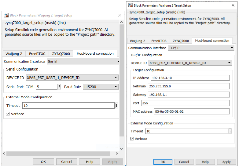
Configuration Parameter |
Selectable Option/Value |
Default Value |
Description |
||||
Communication Interface |
|
Serial |
Select the communication interface external mode uses to exchange data between the host and the target hardware. |
||||
DEVICE ID |
or
|
XPAR_PS7_UART_0_DEVICE_ID or XPAR_PS7_ETHERNET_0_DEVICE_ID |
Select the device ID of the driver module depends on the Communication interface as well as the Hardware reference design file (.xsa).
|
||||
Serial Port: COM |
|
20 |
Enter the ‘COM’ part to which the target is connected. |
||||
Baud Rate |
|
115200 |
Select the baud rate for serial communication. |
||||
IP Address |
|
192.168.1.10 |
Enter the IP address |
||||
Netmask |
|
255.255.255.0 |
Enter the netmask IP address |
||||
Gateway |
|
192.168.1.1 |
Enter the gateway IP address |
||||
Port |
|
256 |
Enter the network port |
||||
MAC address |
|
00-0a-35-00-01-02 |
Enter the MAC address |
||||
Timeout |
|
10 |
Timeout in seconds. |
||||
Verbose |
|
Off |
To view the external mode execution progress and updates in the Diagnostic Viewer or in the MATLAB® command window, select this check box. |
Setting Up Simulink Model for External Mode
The following steps are required to set up any simulink model for external mode simulation.
1.Open Waijung2 Target Setup Block mask and Set the Build options to External mode simulation in the Waijung2 tab and click Apply. Host-board connection tab would appear on the block mask.
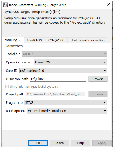
2.From the Host-board connection tab, select the preferred communication interface i.e. serial, tcp/ip and fill in the necessary configurations for the selected interface.
3.In the Hardware tab change the Stop Time to inf.
4.Go to Monitor & Tune dropdown under Run on Hardware group in Hardware tab and select Build for Monitoring for build, compile and upload the model to the target.
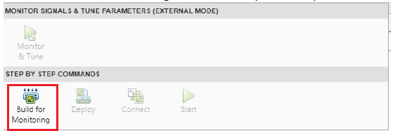
5.Once the build process is finished, open the Control Panel and click the Connect button to start the simulation.
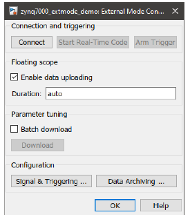
6.If Verbose is ‘on’, open the Diagnostic Viewer.
Typical Application
A demo file is provided at:
[<waijung2 installation directory>\waijung2\targets\zynq7000\demo\extmode_demo]
To load the model file run the following commands in the Matlab Command Window:
>> waijung2.openDemoInCurrentFolder('zynq7000', 'extmode_demo')
Troubleshooting
Q1) The program is simulating, but the tunable parameters are not responding i.e., manual switch, constant block.
A1) Stop the simulation and change the default parameter behavior:
Model Configuration Window > Optimization > Default parameter behavior > Tunable.
Q2) Error on the Diagnostic Viewer: The model that you are trying to run in External mode does not match the application running on your target. Checksum test (TARGET_CONNECT) failed. The host model's structural checksum is [2081348705, 2121790006, 4161585037, 3269416663] and the target application's structural checksum is [1320608190, 1676316499, 1989221354, 3589294337]. Rebuild the model, run it on your target, and start External mode simulation again.
A2) This happens when the user makes a change to the model that is not reflected in the current program running on the target MCU. Re-build and upload the model.
Q3) Warning on the Diagnostic Viewer: Not enough memory on the target to process the packet: EXT_SELECT_SIGNALS
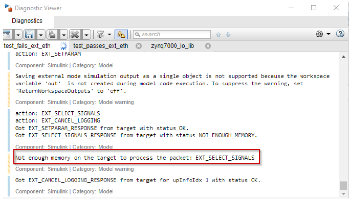
A3) This is because the available heap in the target is not enough for the External Mode functionality. There are several solutions for this problem.
1.Increase the heap in ZYNQ7000 tab in the Target Setup block.
OR
2.Reduce the Duration parameter:
a.In the Simulink Editor, on the Hardware tab, click the Control Panel.
b.Then click Signal & Triggering ... and reduce the duration.
Q4) Failed to connect to the with FreeRTOS and when the stdin and stdout are enabled with UART, the message ‘vApplicationMallocFailedHook() called’ will be printed in the serial monitor.
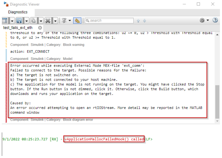
A4) The reason why it occurs because there is no enough heap to initialize FreeRTOS. To solve this, increase the amount of memory in Total heap size reserved for FreeRTOS in FreeRTOS tab in Target Setup block