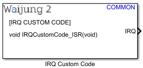
How this block appears in a Simulink model?

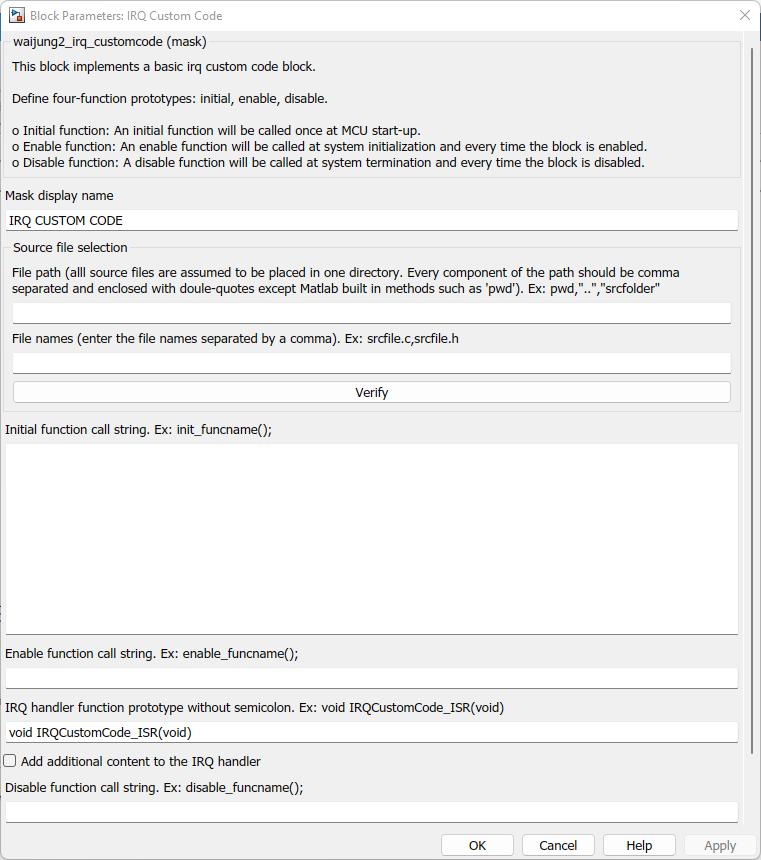
What can be configured?

Configuration Parameter |
Selectable Option/Value |
Description |
Mask display name |
|
Enter display name which appears on the block display. |
File path |
|
Define the path where the files are located. Only one path can be entered and therefore, it is assumed that all files are located in the same folder. A user could either specify the relative path or the absolute path. Every component of the path should be comma separated and enclosed with double-quotes except Matlab built in methods such as pwd. Examples: •pwd,”..”,”srcfolder” •“C:”,“Users”,”admin”,”Downloads”,”srcfolder”
|
File names |
|
Define the files that needs to be included in the build process. Waijung 2 will automatically copy these files to the build directory during the build process. Any number of files can be specified. Each file name has to be comma separated. |
Verify |
|
When you click this button Waijung2 will automatically check whether the specified files exist in the path specified and provide feedback. |
Initial function call string |
|
Custom function call once MCU startup. |
Enable function call string |
|
Custom function call when the Block is enabled. |
Disable function call string |
|
Custom function call script for when the block is disabled. |
IRQ handler function prototype |
|
Function prototype of the interrupt handler (without semi-colon ";" ) |
Add additional content to the IRQ handler |
on--off |
Enable/disable the ability to customize the content of the IRQ handler. If this is Unchecked only the code generated from the Function-call subsystem which is connected to the IRQ output port, will be placed inside the IRQ handler. |
IRQ handler content... |
|
This text field is only visible when the Add additional content to the IRQ handler checkbox is checked. This field can be used to add additional lines of code to the ISR apart from the code generated from the connected function-call subsystem. The generated code from the function-call subsystem will be in place of %[function-call subsystem] keyword. |
|
|
|
INPUT/ OUTPUT Port
Port Name |
Port Type |
Data Type |
Description |
IRQ |
|
Function-call |
Connect a function-call subsystem in Simulink to the output port of this block. |
When to use this block?
When you want to add your own custom asynchronous (interrupt) C code to the system.
How does this block work?
This block can be used when you want to add your own custom C code to the system. To use the IRQ Custom Code Block you need to complete the following steps.
oStep 1: Define include and source files for the custom code.
Use File path edit box to define the path where the files are located. Only one path can be entered and therefore, it is assumed that all files are located in the same folder. A user could either specify the relative path or the absolute path. Every component of the path should be comma separated and enclosed with double-quotes except Matlab built in methods such as pwd.
For example: a) pwd,”..”,”srcfolder”
b) “C:”,“Users”,”admin”,”Downloads”,”srcfolder”
c) “C:\Users\admin”,”Downloads”,”srcfolder”
Use File names edit box to define the files that needs to be included in the build process. Waijung 2 will automatically copy these files to the build directory during the build process. Any number of files can be specified. Each file name has to be comma separated.
oStep 2: Define three-function prototypes: initial, enable, disable.
When generating code for a Simulink block, Matlab creates these three different functions.
▪Initial function
An initial function will be called once at MCU start-up.
▪Enable function
An enable function will be called at system initialization and every time the block is enabled, e.g. in a case where a block is located in an Enabled Subsystem.
▪Disable function
A disable function will be called at system termination and every time the block is disabled, e.g. in a case where a block is located in an Enabled Subsystem.
Your job is to define functions that will be wrapped inside these automatically-generated MATLAB function calls. The function definitions of the prototypes specified are to be found in the included source and header files. Apart from the main function prototype, additional C code lines can also be specified, if necessary, in each of the edit box spaces mentioned below.
▪The Initial function can be defined in the Initial function call string edit box. The Initial function must not have any input parameters or a return value.
▪The Enable function can be defined in the Enable function call string edit box.
▪The Disable function can be defined in the Disable function call string edit box.
▪The Enable function and Disable function must not have any input parameters or return values. These functions will be called every time the system is initialized and enabled/disabled.
oStep 3: Define the IRQ function prototype without the semicolon.
This parameter can be used to define the function prototype of the ISR function. This enables the user to specify any input parameters for the ISR.
When designing the custom C library, it is important to add the header rtwtypes.h where the Matlab typedefs are defined. These typedefs must be used when developing the custom C library functions.
Data type specified in the mask |
Corresponding type definition |
double |
real_T |
single |
real32_T |
int8 |
int8_T |
uint8 |
uint8_T |
int16 |
int16_T |
uint16 |
uint16_T |
int32 |
int32_T |
unt32 |
unt32_T |
boolean |
boolean_T |
Demo
Demo file : esp32_irq_customcode_demo.slx

Description
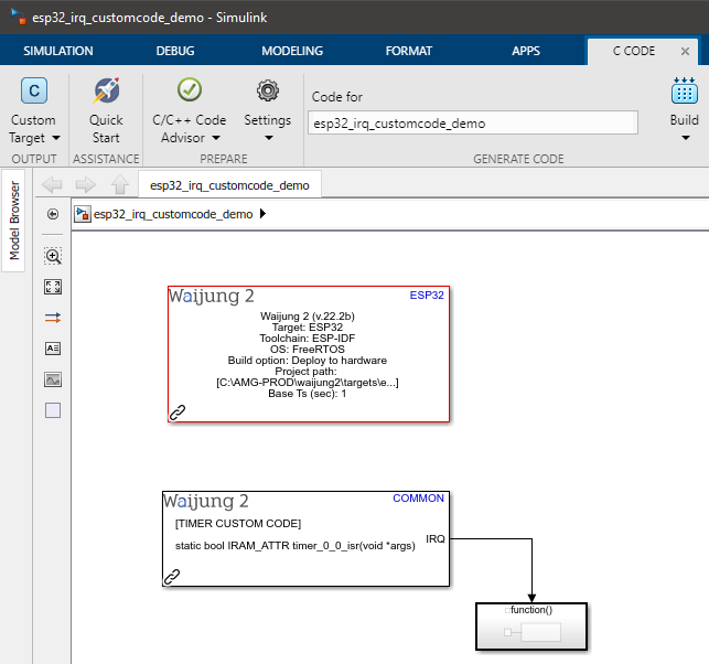
This example shows how to use the IRQ Custom Code Block on ESP32 by implementing a timer interrupt. To observe the interrupt, a GPIO is toggled within the interrupt service routine.
Setup
First, download the irq_customcode_demo_lib.zip and extract the content. Copy the extracted folder to the same folder as the model file. Open the model file from Matlab. In the IRQ Custom Code block mask, browse the Path for include files (*.h) and Path for source files (*.c) to the extracted folder.
An oscilloscope should be connected to the GPIO pin specified in the model (in the example GPIO Pin 2 is selected.)
What should be happening?
After the model file is compiled and uploaded to the ESP32 board, the following output can be seen on the oscilloscope.
