Description
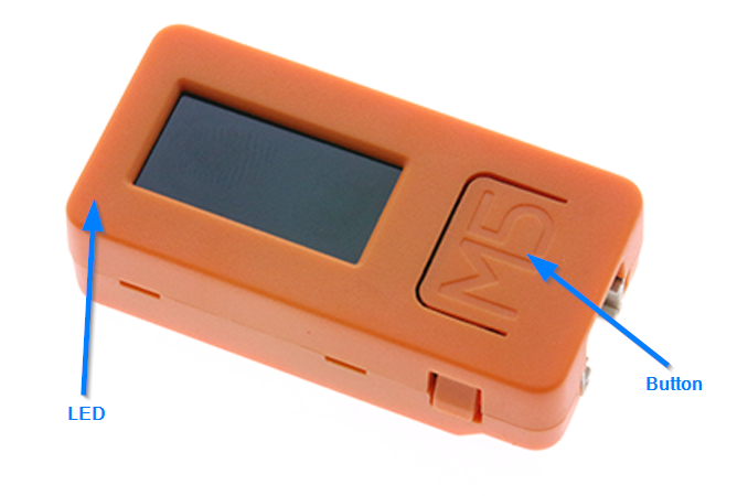
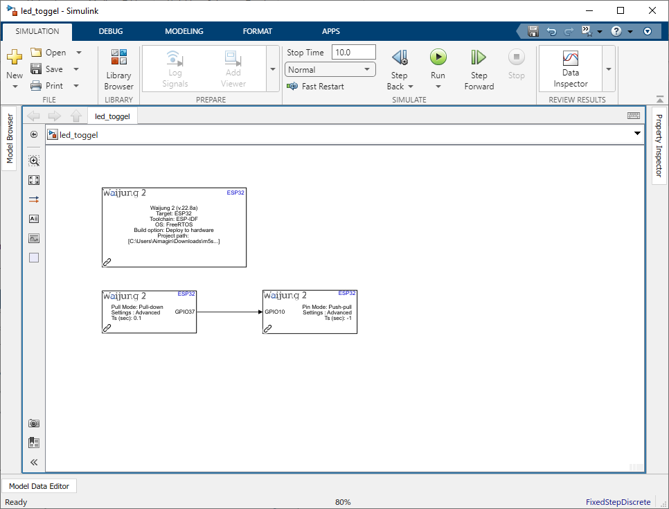
This example demonstrates how to use onboard button and LED to ON the LED when the button is pressed. For this, GPIO37 (push button) is used as the input and GPIO10 is used as LED.
Note: Before trying the tutorial please install the patch for digital input block.
Hands-on Simulink model
Step 1: Open Matlab Simulink
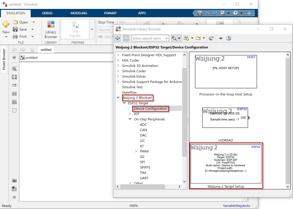
Step 2: Import Waijung 2 target setup block from library browser
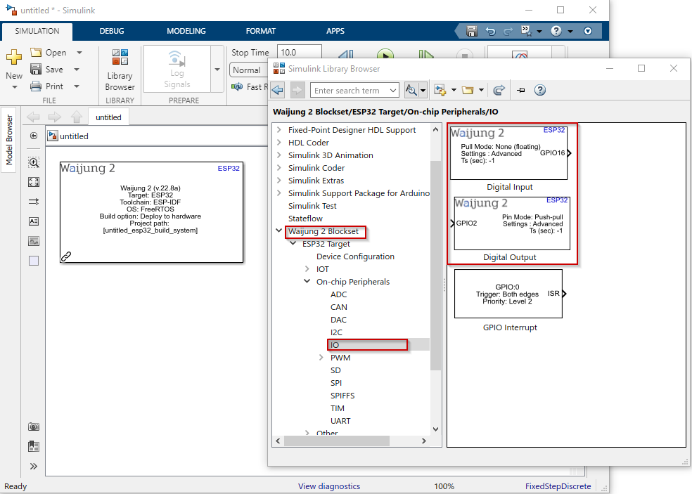
Step 3: Import digital input and digital output blocks to the model
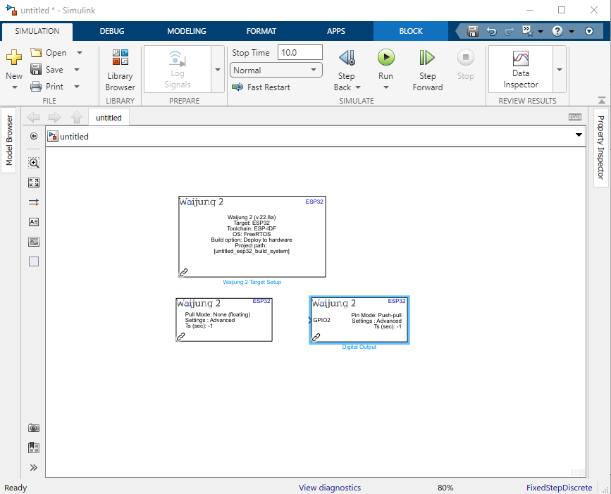
Step 4: Change the mask parameters of each block according to the hardware board
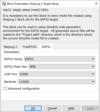
Change following parameters in the ESP32 tab in Waijung 2 Target Setup block
1.Select the correct COM port
2.Change the Baudrate to 115200
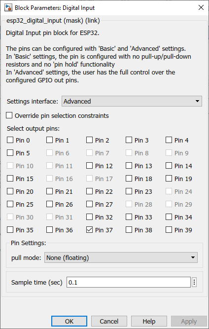
Change the Digital Input block mask parameters
1.Select Pin37 (for push button)
2.set the Sample time to 0.01
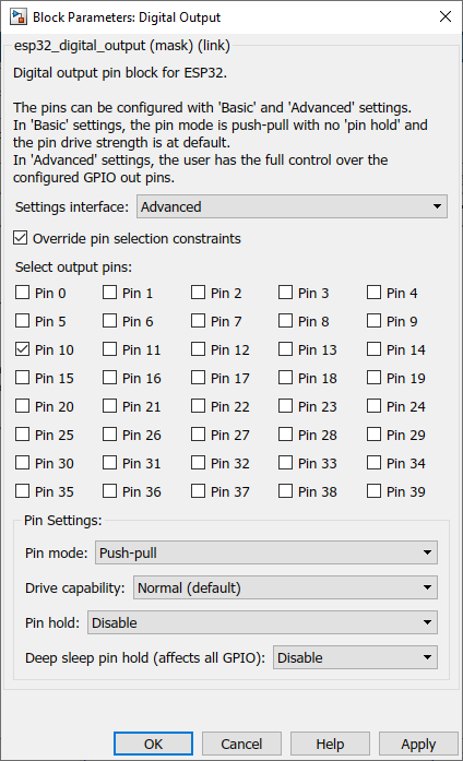
Change the Digital Output block mask parameters
1.Enable Override pin selection constraints check box
2.Select only the Pin 10 (for LED)
Step 5: Connect the Digital Input output port with Digital Output input port and save the model file properly
Step 6: Go to Apps tab and select Embedded Coder. Then Go to C CODE tab and Build it

Step 7: Once the Simulink model is built and upload it to ESP32 successfully, if the push button is ON the LED will be ON.
Simulink model file: led_toggel.slx