Design overview
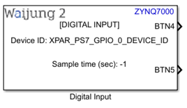
Digital input block appearance in a Simulink model,
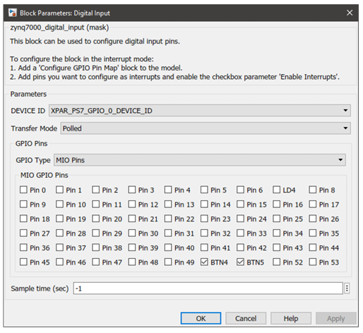
Digital input block mask overview,
Digital Input Block input interfaces
Name |
Type |
Range |
Description |
N/A |
|
|
|
Digital Input Block output interfaces
Name |
Type |
Range |
Description |
Pin <x> |
Default: uint32 The data type of the port can be changed using Configure GPIO Pin Map block |
Expected values 0 or 1 |
<x> represents the selected pin number. For each selected pin in the mask, a separate port will be created.
This format is shown only when the Transfer Mode parameter is configured as Polled. |
IRQ |
Function-call |
|
A Function-Call Subsystem should be connected to the port.
This format is shown only when the Transfer Mode parameter is configured as Interrupted. |
Digital Input Block behavior
Digital input block can be used to configure GPIO pins via MIO and EMIO interfaces. Using this block the pins can be configured to work in either interrupted or polled mode. The pins are labelled from 0-117. Pins 54-117 are connected through the EMIO interface and have to be mapped during the hardware design stage using Vivado Design Suite. To assign a custom label for a certain pin for convenience, Configure GPIO Pin Map block can be used. This block can also be used to assign the port data type for each individual pin. It is optional to use the Configure GPIO Pin Map block in Polled mode. However, when using the Digital Input Block in Interrupted mode, it is mandatory to add the said block to the model as interrupt pins are specified using that block.
Digital Input Block configuration
Configuration Parameter |
Selectable Option/Value |
Description |
|
DEVICE ID |
XPAR_PS7_GPIO_0_DEVICE_ID
|
Depending on the peripheral availability in your hardware design created using the Vivado Design Suite, available device-ids will be shown. |
|
GPIO Type |
MIO Pins |
EMIO Pins |
Select the GPIO interface. Depending on the selected interface, respective configurable pins are shown. In the case of EMIO, the pins displayed on the block mask may or may not be available in your actual hardware design. |
Transfer Mode |
Polled |
Interrupted |
Select the transfer mode.
|
Interrupt Type |
XGPIOPS_IRQ_TYPE_EDGE_RISING |
Select the interrupt type. |
|
XGPIOPS_IRQ_TYPE_EDGE_FALLING |
|||
XGPIOPS_IRQ_TYPE_EDGE_BOTH |
|||
XGPIOPS_IRQ_TYPE_LEVEL_HIGH |
|||
XGPIOPS_IRQ_TYPE_LEVEL_LOW |
|||
Pin <x> |
On |
Off |
The pins to be configured using the block can be selected by toggling the check boxes. |
Sample time (sec) |
-1 (inherited) or specify |
Specify the sample time for the block in seconds. |
|
Digital Input Block limitations
The known limitations associated with the block are:
•By default, in the block mask display all the pins (0-117) are available for the user to configure. However, depending on the hardware design (XSA file provided in the model Target Setup Block) some pins might not be available for configuration.
•Depending on the hardware development board, some pins could be hardwired as either input or output. Waijung 2 block set does not have the ability to acquire this information and therefore, will not be able to indicate these pins in the block mask.
•PIL interrupt; Level low or Level high
oCode architecture doesn’t support this type of interrupt testing with the PIL mode. This is mainly because when it is in the level low or level high interrupt state it won’t change the state.
•In PIL mode and External mode if interrupt types level high and/or level low is also used, please note that these modes will not work until the physical signal state of the pin has been reset to not trigger the interrupt by the user. This is due to the interrupt service routine (ISR) interrupting and taking priority over the normal scheduling of tasks. Please be mindful of the signal state of the input pins that uses level low or level high interrupt types, particularly when using these modes.
For an example if an interrupt is configured to trigger low level and the model is set to run on PIL or External mode, only the interrupt service routine (ISR) will be triggered continuously until the physical signal state of the pin is set to high by the user. In this case, the target will not function as expected in PIL mode and External mode since the ISR is blocking its normal scheduling process.
Troubleshooting
Typical application
Several demo files are provided at:
[<waijung2 installation directory>\waijung2\targets\zynq7000\demo\gpio_demo]
To load the model file run the following commands in the Matlab Command Window:
•Demo 1: waijung2.openDemoInCurrentFolder('zynq7000', 'gpio_demo1')
•Demo 2: waijung2.openDemoInCurrentFolder('zynq7000', 'gpio_demo2')
•Demo 3: waijung2.openDemoInCurrentFolder('zynq7000', 'gpio_demo3')
•Demo 4: waijung2.openDemoInCurrentFolder('zynq7000', 'gpio_demo4')